Table of Contents
Run 70 HV Noise
HV drift
One mode of operating this contact-free detector is to slowly drift the applied HV bias to cancel accumulating counter-bias and maintain an approximately constant effective crystal bias. Operated in this manner, the noise width was observed to rise with crystal bias.
Balanced Psum
Different results were obtained depending on the energy quantity used. These plots show the results from using a balanced sum of all 6 channels, individually fitted with a calculated OF template.
First, by comparing the position of the 60keV line in 0V data to the 14 keV line in biased data, the NTL gain, and thus crystal bias, can be measured. Here, HV0 refers to the starting HV setting after ramp-up and pre-bias. This allows measurements to be compared without the effects of HV loss via HV leakage current and vacuum-gap drop.
| Figure 1 |
|---|
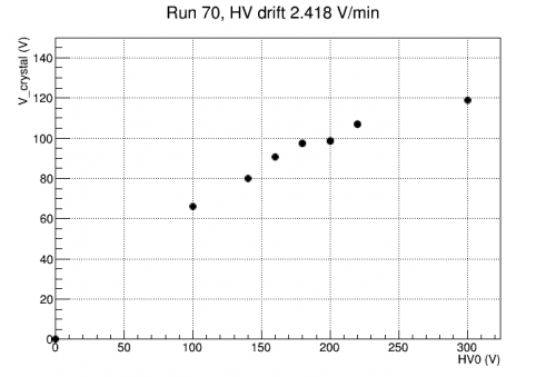 |
| Effective crystal bias vs applied HV. |
Alternatively we can calculate the apparent Luke gain at zero energy based on the quadratic calibration from the 14keV and 18keV Am lines, which should reduce the effects of saturation. At 0 volts, we still assume a linear calibration to the 60keV line (whose amplitude is less than the 14keV line at any of the non-zero voltages observed). We can also calculate V_crystal based on the applied HV, the reduction based on current leakage (around 1%), the reduction due to counterbias during the HV rampup, and the drop across the vacuum gap. This gives a result similar but not quite the same as the apparent bias based on the gain, V_Luke. And there are outliers in some cases, which may point to inaccurate calibrations in those cases.
| Figure 2 |
|---|
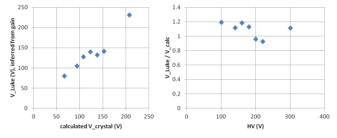 |
| Comparison of calculated and gain-inferred crystal bias. |
The figure below shows the width of the total phonon noise, calibrated using the 60 keV line at 0V. This noise rapidly increases above 80V crystal bias. It is not understood why the amplitude of the 0V noise is a factor of ~2 higher than previous runs.
| Figure 3 |
|---|
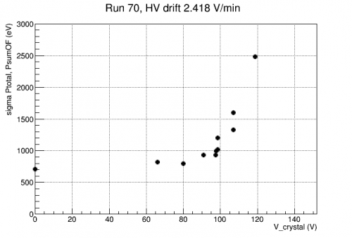 |
| Total phonon noise as a function of crystal bias |
Finally, the effective noise level, given NTL gain, is found to have a minimum value around Vcry=98 V (HV0=180 V).
| Figure 4 | |
|---|---|
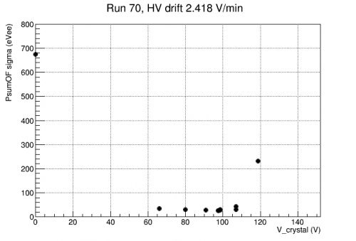 | 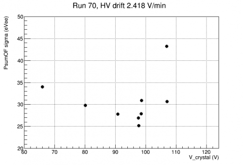 |
| Effective noise as a function of crystal bias. Left: Full range. Right: Zoom on minimum. | |
PT versus Psum
Another look at the noise width was based on unbalanced PT and unbalanced Psum.
| Figure 5 |
|---|
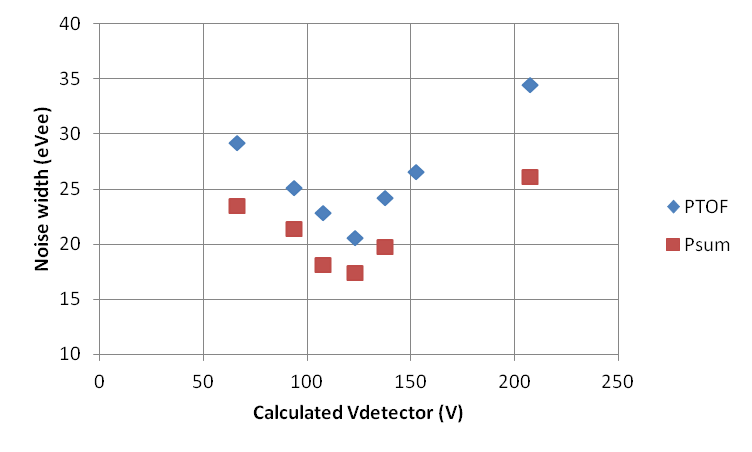 |
| Noise versus bias using unbalanced phonon amplitudes |
Note that
- psum produces smaller noise width than pT. This is likely due to DCRC glitches producing problems with time-synchronization of the traces of the individual channels
- Unbalanced psum produces smaller noise width than balanced psum. This is likely due to the QET biases of the inner-ring channels being set high, above their oscillation regions. This reduces their gains, and since they seem to have higher noise, leaving them underweighted could improve the apparent noise width.
Approaching the noise width target, 15 eVee
To do the n,gamma measurement, we'd like a noise width of 15 eVee or less, which would probably produce an effective threshold of 15*5 = 75 eVee, which if we assume a yield of 0.15 yields a threshold of 75/0.15 = 500 eVnr. This would allow us to see the highest energy signal peak.
The lowest noise width seen in this data is 17.4 eVee seen at HV=180V (Vcrystal = 125-140 V) after calibrating unbiased psum. The beginning-of-run randoms show narrower noise then end-of-run randoms, possibly due to noise that occurs late in the run… if we look only at BOR randoms the noise width is 16.6 eVee.
We may be able to use an unbalanced phonon quantity for the calibration but it would likely introduce a position dependence - a fiducial cut may be necessary.
The unbalanced case gives a somewhat better noise width, possibly because in these data, the QET biases of the inner-ring channels has been elevated
HV const
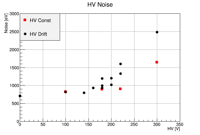
The noise was also evaluated for series where the applied HV was held constant. During such series, the signal fell linearly as the NTL gain dropped with crystal bias due to accumulating counter bias. However, the absolute phonon noise level held constant. The figure below shows the magnitude of this noise, as measured by a balanced PsumOF quantity and calibrated from the 60keV line at 0V. The HV drift data from above is included for comparison.
| Figure 6 |
|---|
 |
UPDATE
I took another look at the noise in one of the constant HV cases, and did see some change over time. The plot below compares a case where HV was set to a constant 180V (V_crystal around 120 V) to the noise-versus-bias in the drifted case:
| Figure 6.1 | |
|---|---|
 |  |
In the second plot above, we see that as V_detector falls in the constant HV case, the total phonon noise is not entirely flat. In fact there seems to be a period (about 25 to 40 minutes) where the noise is lagging, but before and after that it tracks the normal pattern.
In fact, for that same “lag period”, in the drifted-HV case we see the noise is elevated. This turns out to be a pattern seen in multiple 180V-drifted series. There's no obvious explanation for this repeating pattern.
Comparing Run 70 to Run 66
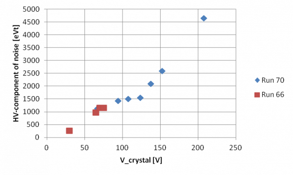
To compare HV noise between the two runs, we should do the following:
- use balanced Psum or PT quantities
- use drifted-bias results from Run 70
- subtract the 0-Volt noise sigma in quadrature from the total noise sigma (in eVt units)
- use best estimates of the crystal bias
Below is an approximate attempt to do this. From this perspective it looks like the HV noise is not noticeably improved in the current setup.
| Figure 7 |
|---|
 |
UPDATE
Figure 7 above was an approximation based on scaling upward the noise widths produced with unbalanced calibrations. Below I instead use Nick's results with balanced pSum calibrations (with one exception: I redid the 300V result, whose Am lines are hard to identify).
| Figure 8 |
|---|
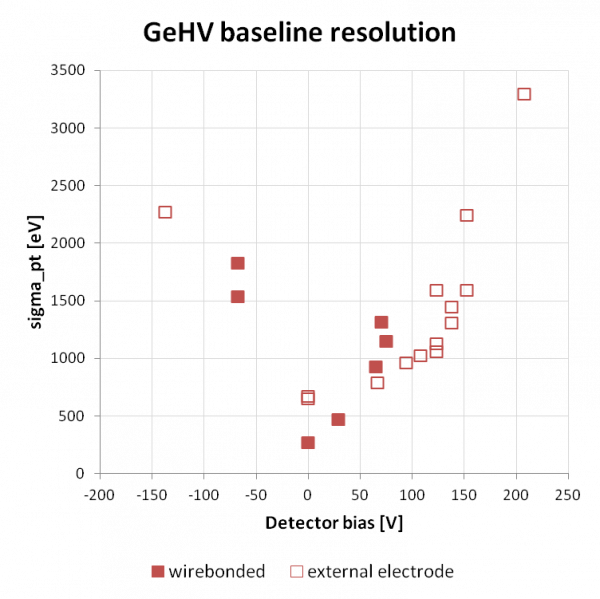 |
This figure suggests a significant improvement with the current external electrode versus the standard wirebond setup.
To really claim we have improved the HV noise, this should be redone more carefully, to match the Run 66 calculations as closely as possible. We now have activation lines, so we could use those instead of Am to match Run 66 (we'd need to redo the bias-scan data). We may want to tune the QET biases to more closely match Run 66.
We should consider whether the improvement, if it's real, may be caused by the improved HV wiring that bypasses the SQUET. I think it's unlikely, in part because SiHV has much lower HV noise even with the through-the-SQUET HV wiring.