Table of Contents
Run 45
Cryogenics
Summary of Maintenance Work
Prior to this run, a total of five striplines had been installed in the fridge. Their problems are summarised in Table 1.
| Table 1: Summary of Striplines installed in K100 prior to Run 45 | |
|---|---|
| Stripline | Issue |
| 19 | None |
| 20 | One broken trace: Qo bias |
| 21 | Many broken traces |
| 27 | Four broken traces: QET A Return, Feedback Coil B (recent), Feedback Coil C, QET D Return |
| Candy | SQUID Bias B shorted to SQUID Bias B Return & Qo Source shorted to Qo Drain |
As it stands, Stripline 27 has been rather robust and hence Stripline 21 is surplus to requirements. Additionally, until Candy (MIT-design) is repaired, it cannot be used. As the bottom heat sink for the striplines runs rather close to the 100 mK can, removing these two striplines would increase the separation, thus reducing the possibility of a thermal short between the 4.2 K and 100 mK stages. Therefore, Stripline 21 and Candy were removed from the fridge.
This presented an opporutnity to polish the 30 mK and 100 mK stages, which was availed. On the 30 mK stage, a copper spool is fastened to the mixing chamber by seven M3 socket-head, stainless steel screws at a torque of 10 lb-ft and one 10 mm nut. A copper can is then fastened to the bottom of this spool by six M3 socket-head, stainless steel screws, again at a torque of 10 lb-ft. The tower's 10 mK ears are fastened to the copper adapter plate by six M3 socket-head, stainless steel screws at a torque of 5 lb-ft, and in turn the adapter plate is secured to the bottom of the 30 mK can by twelve M3 socket-head, stainless steel screws at a torque of 5 lb-ft. Both the 30 mK copper spool and can were polished before restoration.
On the 100 mK stage, a narrow copper cylinder screws into the cold plate with six M3 socket-head, stainless steel screws at a torque of 10 lb-ft. A wider copper cylinder then connects to the bottom of this with six M3 socket-head, stainless steel screws at a torque of 10 lb-ft. Both cylinders were removed, polished and reinstalled.
The 30 mK stage thermometer wires are wrapped around the 30 mK copper spool, and therefore it's removal allowed for restoration of the tower thermometer. Two wires were found to have popped out from the connector pins to which they were soldered. These were resoldered into place. However, it was decided not to use silicon sealant to make the joints more permanent before running at least one test at base temperature. As a result, the pins were wrapped in PTFE tape.
Additionally, the wire that the tower thermometer is connected to typically runs down the side of the 30 mK stage. To prevent any possible contact between the 100 mK and 30 mK cans, ease of installation was sacrificed by shortening the wire so that it does not drop below the bottom of the 30 mK can. The subsequent tower installation was far easier than expected, and the tower thermometer is confirmed to be working at base temperature. This is the first time we have had both the RuO2 H35 thermometer on the mixing chamber and tower thermometer working at base temperature, so are now able to monitor the temperature gradient.
Over Christmas and into the New Year, the mixing chamber and helium cold trap were connected directly to the turbo pump and evacuated. This continued while other maintenance work was being carried out in January. The mixing chamber and cold trap were evacuated for a total of 4 weeks. After carrying out a couple of througput tests (both the Minnesota and Berkeley variants) multiple times after blowing out the liquid nitrogen, no improvement was apparent from pre-Christmas rates. If anything, the tests yielded a worse throughput rate by a factor of two (ie. six times worse than what is usually expected). One possible explanation is the higher mixing chamber temperature of 90-105 K during these tests, thus yielding poorer rates. No data is available to back up this hypothesis.
Base Temperature
The poor throughput rate did not appear to affect the base temperature. If anything, the mixing chamber reached a slightly cooler base temperature, when compared with Run 43, of 59.2 mK approximately 20 hours after completing the manual condensation procedure (ie. valve V6 on IGH fully open). For reference, approximately 350 mbar dump pressure of mixture (17.5 l) was condensed and the still pressure was 60 ± 2.5 μbar. At around this time the tower temperature was 72.1 mK, or in other words a difference of around 13 mK. It should be noted that the tower thermometer is secured to a copper plate mounted within the source holder, which lies above the crystal, and therefore is close to the furthest point of contact from the mixing chamber.
Plugging DCRC31 into DIB 1 did not cause the tower nor mixing chamber temperatures to increase. However, connecting DCRC31 to DIB 2 resulted in both the tower and mixing chamber temperatures increasing to 124 mK and 75 mK respectively. This is possibly due to the noise also witnessed during Run 41 and discussed below.
A single-shot test was performed, this time keeping an eye on the tower thermometer to estimate what temperature may have been reached during Run 43 when G114 (AJA 100 mm v6 IZIP) was tested. The tower temperature reached a minimum of 52.1 mK, which could imply that the G114's phonon channel Tcs lie below 55 mK.
After recondensing and recirculating 350 mbar dump pressure (17.5 l) of mixture, mixing chamber and tower temperatures of 58.0 mK and 66.7 mK respectively were achieved. The still pressure was 65 ± 2.5 μbar, and the cold plate and still temperatures were around 160 mK and 1.01 K respectively.
Although the tower temperature has been decreasing steadily over the last fortnight, the mixing chamber temperature has remained fairly constant. The tower temperature also recovers relatively rapidly following long periods of flashing. This would imply that the thermal contact between the tower and mixing chamber is fine, and one simply needs to wait for the temperature difference to decrease.
As of the evening of Sunday 9th January, the tower temperature was 62.8 mK.
Future Efforts to Reduce Base Temperature
For the past few runs, it has been difficult to maintain a stable 1 K pot temperature below 1.64 K. This is rather warm, and means the mixture entering the heat exchangers from the condenser is slightly warmer than desired. In turn, this would result in a higher base temperature. It is likely a sign that the He-4 pump requires a service. Unlike the He-3 circulation pump, the 1 K pot pump should be relatively trivial to open up and clean. It is hoped to complete this before the next run. It is expected that this should reduce the base temperature by 2-5 mK.
The 600 mK rod runs very close to the 30 mK and 100 mK cans, and there is always the possibility of thermal contact. Prior to Run 41, thin polyethylene pieces were tied to the 600 mK rod with dental floss in certain places to provide a layer of insulation in case of contact. Another possibility is removing the 600 mK rod completely. From data taken during the first couple of runs with this cryostat, the base temperature appears to have decreased from 35 mK to 29 mK after the rod was installed. However, it is possible that the rod is doing more harm than good after considerable thermal cycling, and hence movement of parts within the fridge. It may be worth attempting a run without the rod to determine if does make a difference.
Having said that, an empty run was attempted recently in Run 40, and the current base temperature this run is comparable to it. It is possible that heat transfer through radiation between the 4.2 K IVC and mixing chamber may be responsible for a relatively high base temperature. There was no attempt to shield the mixing chamber from this.
Electronics
Charge Noise on DIB 2
As witnessed in Run 41, when a DCRC is connected to DIB 2, oscillations appear after the FET heater is turned on and the FET has thawed. They are of the same amplitude as that witnessed before: approximately 350 mV. A number of different combinations of stripline and SQUET card have been attempted over this run and Run 41, but no improvement is evident.
It is unknown where the problem lies and whether it is worth investigating. For now, a shorting board has been plugged into Stripline 20's ebox feedthrough to ground the charge channels on DIB 2.
Broken Feedback Coil B Trace on Stripline 27
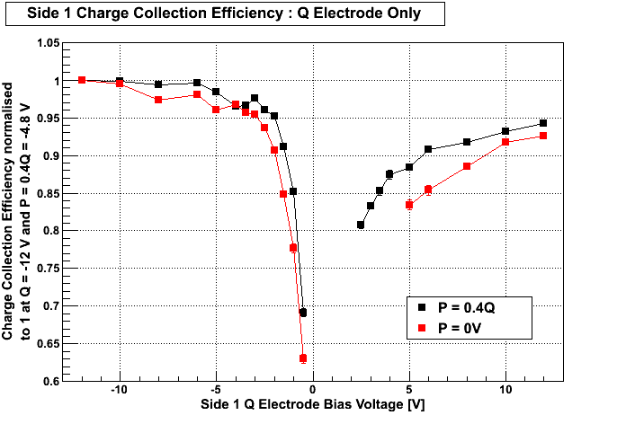
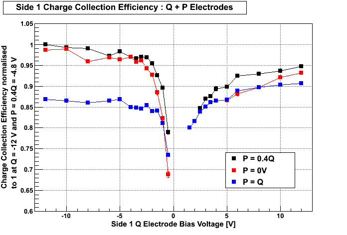
Charge Collection Efficiency Measurements
| Figure 1. |
|---|
 |
| Figure 2. |
|---|
 |