Table of Contents
Run 38
Description of Setup
| Table 1: Run 38 Setup. | ||
|---|---|---|
| Detector | 51 pF mica capacitor | |
| Tower | T1 | |
| Face | 2 | 5 |
| Side coax | ZB1-1-9 | Flexible v5 |
| SQUET | ZC70 | ZC23 |
| Stripline | #27 | #19 |
| Readout | DCRCv3 | |
Record Length: 26.2144 ms
Lookback time: 100 us
Averages: 20
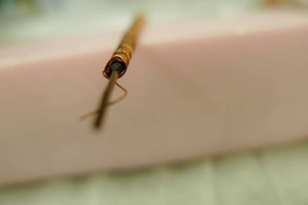
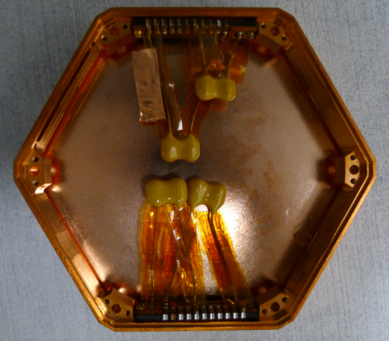
This run tested the flexible side coax “Flexible v5”. The conductor is 20AWG copper wire that has been covered in carbon colloidal (graphite) paint. The insulator is polyolefin heat shrink tubing and the shield is copper tape. The hope is the carbon colloidal paint between conductor and insulator will reduce microphonic pick up of the cables. The detector for this run is a standard CDMS 3“ detector housing with two 51pF capacitors acting as the detector. Figures 1 and 2 show an example of what the gate cable looks like, and Figure 3 shows what the detector looks like.
| Figure 1: Example cable along the length. |
|---|
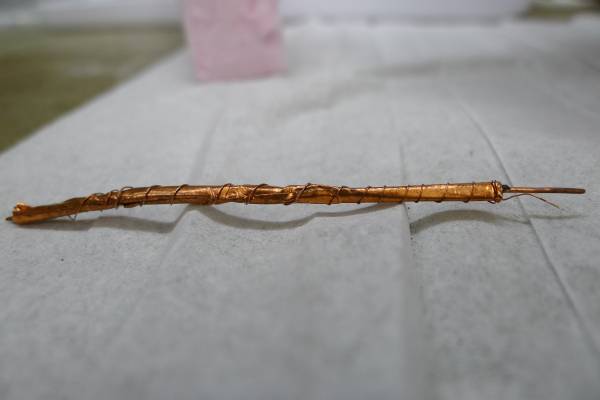 |
Note, the cable has wire wrapped around the length because it was an early attempt to provide extra grounding for the gate wire. However, this grounding was ultimately not hooked up to anything.
| Figure 2: Gate cable along the axis. |
|---|
 |
| Figure 3: Fake detector used to measure the noise |
|---|
 |
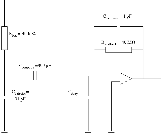
The SCAB and SCHUBA for this setup are identical to that of Run 25. Refer to Figure 4 for a circuit diagram of the set up of this run.
| Figure 4: Circuit diagram of the detector readout |
|---|
 |
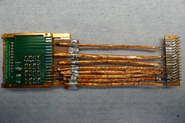
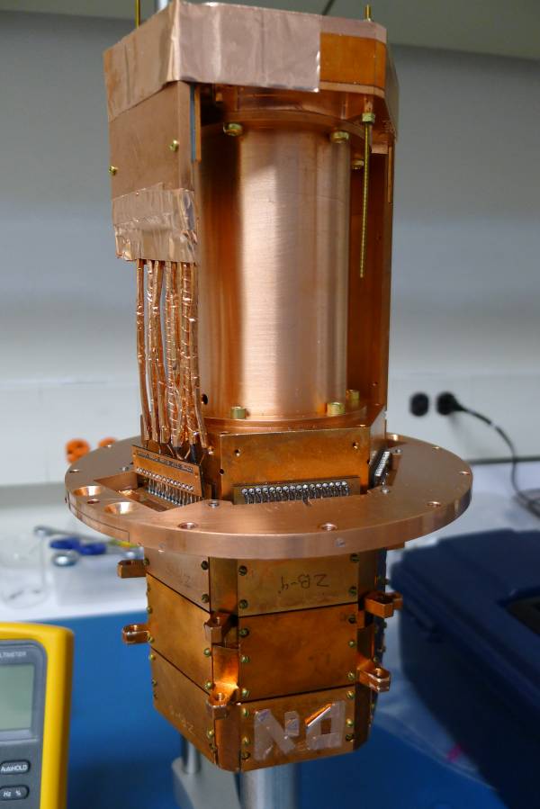
Note that extensive measures were taken to ground the shields of the cables on the flexible side coax. There is copper wire around the shield of the gate cable, the most susceptible conductor to microphonic pickup (see Figure 1). Note that this copper wire was ultimately cut off at the ends because it was unfeasible to ground it. In addition to this, all the shields were soldered to copper foil that is connected with copper tape to the copper back plate (see Figure 5). The soldered parts of the shield were then tightly wrapped in copper tape in order to press the copper foil flush against the copper back plate. After the SCAB was plugged into the tower, it was further pressed against the tower with copper tape to ensure the SCAB is kept in place during cool down as well as ensure good grounding (see Figure 6).
| Figure 5: The completed flexible side coax. |
|---|
 |
| Figure 6: Flexible Side Coax mounted on the tower. |
|---|
 |
Data Summary
The cable was tested to determine its ability to resist microphonic noise compared to the vacuum side coax. Accordingly, Power Spectral Densities (PSDs) were taken in a number of different conditions:
- At Rest: no induced vibrations
- Weight dropped from 10cm
- Weight dropped from 20cm
- Weight dropped from 30cm
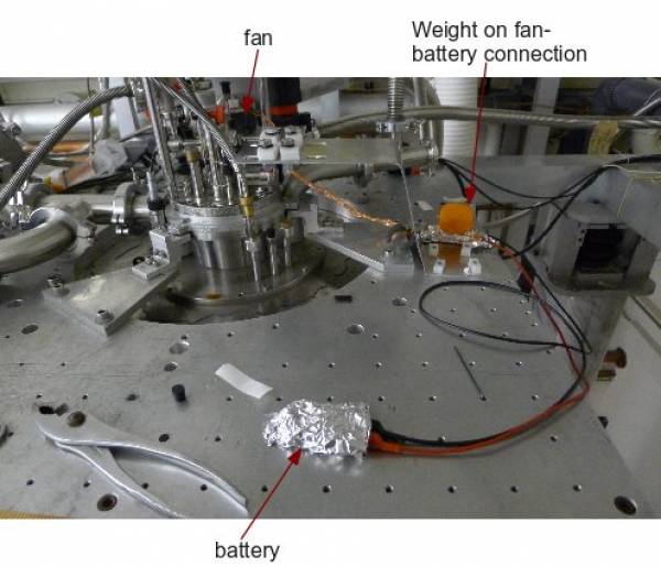
- Fan, No Contact: Computer fan running, making contact with nothing (See Figure 7)
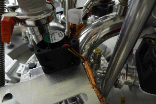
- Fan, Contact: Computer fan hitting paper taped to the 1K Pot needle valve (See Figure 8)
| Figure 7: Set up of the fan to induce vibrations. Note the use of foil to combat RF leaks |
|---|
 |
| Figure 8: Close up of the computer can hitting paper on the 1K Pot needle valve |
|---|
 |
To combat RF leak, aluminum foil was wrapped around the battery and cables. To eliminate bias, each of these tests were run with the following DCRC board configurations:
- DCRC 32 connected to flexible side coax, DCRC 33 connected to vacuum side coax
- DCRC 33 connected to flexible side coax, DCRC 32 connected to vacuum side coax
- DCRC 32 connected to both side coaxes
- DCRC 33 connected to both side coaxes
All 24 of these PSDs can be found on the run diary page for 2013/07/23. Also on that page is a profile of each individual cable under At Rest, Fan No Contact, and Fan Contact conditions.
| Figure 9: Example PSD taken from Configuration 3, At Rest |
|---|
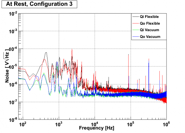 |
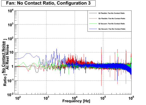
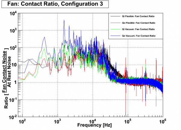
Based on those PSDs, it appears the vacuum coaxial cables have slightly less net noise, especially in the 1 kHz to 2 kHz region. However, we are more interested in the cables' susceptibility to noise, so it is more relevant to look at the ratio of a cable's noise when mechanical vibrations are induced to the noise when it is at rest. Figures 10 and 11 show these ratios for each charge channel for Fan, No Contact (Figure 10) and Fan, Contact (Figure 11). Configuration 3 was chosen because it was the least noisy configuration that had complete data.
| Figure 10: Each charge channel's susceptibility to noise at Fan, No Contact conditions |
|---|
 |
| Figure 11: Each charge channel's susceptibility to noise at Fan, Contact conditions |
|---|
 |
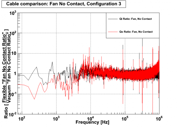
With these ratios as a basis for each channel's susceptibility, we can now compare the performance of each of the cable designs. Figures 12 and 13 show the ratio of susceptibility of each design. Notice, the 1 kHz to 2 kHz region in both these figures: the flexible side coax seems less susceptible to microphonic noise than the vacuum side coax, even though its net noise was higher.
| Figure 12: Comparison of design performance at Fan, No Contact conditions |
|---|
 |
| Figure 13: Comparison of design performance at Fan, Contact conditions. |
|---|
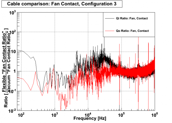 |
In general, it seems the flexible side coax “Flexible v5” is at least as resistant to microphonic noise as the current vacuum design, which means it has potential to be a viable replacement for the vacuum side coaxes.
Cable Capacitance
In order to measure the capacitance of the cables, we built four 6-inch cables of the same design. These cables where then put in parallel, and we used a Digital Multimeter (DMM) to measure the capacitance of that setup. The resolution of the DMM was very restrictive, but, for the aforementioned setup, it fluctuated around 60pF, occasionally slipping up to 70pF or down to 50pF. Thus, we determined the capacitance to be 30±5pF/foot. This is actually less than predicted value of 45.6±3.6pF/foot. This predicted value is calculated from the formula

where κ is the dielectric constant of the insulating layer, ε0 is the permittivity of free space, b is the radius from the central axis of the cable to the inside of the shield layer, and a is the radius from the central axis to the outside of the conducting layer.
Ideally, we would like to decrease the capacitance of the Flexible v5 design to reduce noise. The ultimate goal is to get this capacitance <15 pF/foot. However, this will be difficult. The best dielectrics readily available to us have κ ≥ 2.1. We know that the inner radius of the superconducting wire plus a layer of carbon colloidal paint is ~.25mm and that we can use PTFE dielectric (κ = 2.1). Using equation 1 above, we can solve for the amount of PTFE needed to produce a cable with capacitance 15pF/foot:

plugging in the above value, we see we need ~2.6mm radius of PTFE. This corresponds to ~70 layers of PTFE tape. Unless we consider other dielectrics… (perhaps vacuum, then b = 0.78mm).
However, we have come up with two modifications to Flexible v5 that could lower it's capacitance
- Two layers of PTFE heat shrink, giving a theoretical capacitance ~21pF/foot
- “Air” dielectric aiming for ~15pF/foot (Note that an “air” dielectric would become a vacuum dielectric in the IVC).
Lowering cable capacitance probably won't have a strong effect on the results we have gotten from Run 38. However it will become a very important topic when considering getting rid of the tower in favor of a side coax going straight from the detector to the SQUET cards (See section Source of Noise).
Source of Noise
The noise displayed on the PSD can be predicted from the following equation

Where
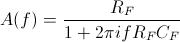
And CD is the capacitance of the detector, Cp is the parasitic capacitance (which cable capacitance is part of), CF is the feedback capacitance, f is the frequency, RF is the feedback resistance, Rb is the bias resistance, k is Boltzmann's constant, and T is the temperature of the bias and feedback resistors.
This equation can be considerably simplified to 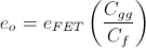 , at frequencies >10kHz. Justification of this can be found on this PDF: approximationanalysis.pdf
However, the unexplained noise in our signal falls in the 1kHz-10Hkz region, so this approximation is not accurate enough to explain that noise. But, it is unlikely that noise is due to parasitic capacitance. The cable capacitance is only a small part of that overall parasitic capacitance. The parasitic capacitance for the standard CDMS setup is ~100pF and consists of the side coax, tower face, SQUET traces, solder joints etc. (Note, these components are all in parallel to each other, so the contribution of each of those terms adds normally to the overall parasitic capacitance.) Since the capacitance of Flexible v5 is ~8pF compared to the ~4pF of the vacuum side coax, the parasitic capacitance should have only gone up 4pF from this new set up. This is a 4% change, which would not lead to the order of magnitude increase we see in the noise at 1kHz-10kHz. This would amount to less that 4% of the noise since the parasitic capacitance is not the only term contributing to noise in those frequencies (see the PDF above).
Future Plans
Since there is no good explanation of the source of the noise from the above analysis, it has been suggested that maybe the natural vibrations of the fridge are causing this noise. The carbon colloidal paint was not sealed on to Flexible v5 with anything but the heat shrink tubing, so it is likely that the paint could have chipped, leaving the exposed part of the cable susceptible to microphonic vibration. Then, any natural vibrations from the fridge (such as those coming from the 1K pot pump) would be seen on Flexible v5 but not the vacuum coaxial cable. This will be the focus of the next flexible side coax run: Flexible v6 will be identical to v5, only the cable will be wrapped in kapton tape after the carbon colloidal paint as been applied. This should provide a seal for the paint, eliminating the possibility of chippings.
While this is going on, we can work on the etching process for the NbTi wire, which will be the conductor for future flexible side coax tests.
Additionally, we are looking for a way to induce vibrations in the cable from within the tower. We have tried piezospeakers from within the detector housing before, but this did not induce enough vibration (perhaps due to the cryogenic temperatures).