| Status | Run 76 beginning. Warming up after LN2 transfer - IVC showed a leak during LN2 blowout. Pumping out cryostat vacuum jacket overnight. MC and Still heaters are on. |
| 0910 | Turbo pump failure - turbo pump is off, cryostat vacuum jacket pressure high. |
| 0920 | Get turbo pump started again. Start pumping CVJ with scroll pump - CVJ pressure is very high. |
| 0935 | Scroll pump on CVJ = 0.19 mbar and slowly falling |
| 0945 | Scroll pump on CVJ = 0.12 mbar. Slowly switch to Turbo |
| 1005 | Turbo on CVJ = 4 ubar. With Turbo valved out for 1 minute CVJ = 0.12 mbar |
| 1020 | Drop main bath, erect clean tent |
| 1035 | Remove bottom of IVC |
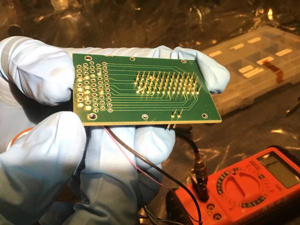
| 1115 | Found bent pin on interposer board, was the cause of the open connection to the inner motor of the new source mover. Attempting to straighten it caused it to break, now soldering in a new pin. |
| 1150 | Reconnect interposer and SQUET |
| 1200 | Quick electrical check is good on all 3 cables. |
| 1400 | Close IVC. |
| 1400 | Electrical check after cap on is good except, cable 1 SQUID B reads high (probably not a problem). |
| 1411 | Tighten bolts on IVC. Starting pumping. |
| 1420 | Started pumping on the IVC with the scroll pump to 0.1 mbar and switch to turbo beyond that |
| 1525 | Leak Detector on IVC ~ 54 pbarL/s. |
| 1530 | Squirt He around bottom IVC joint. No leak detected. Switch back to turbo pumping. |
| 1600 | Working on Dsub-25 connector at end of Fridge Thermometer Cable 1. Attach wires from RuOx thermometer to #2 on connector (using LakeShore scanner manual). Try plugging into scanner - fails to read. Eventually using a multimeter find that the wire map we wrote a while ago is in error - the V+/I+/I-/V- identifications are not correct. (Same-side leads read ~ 300 Ohm, opp cam1_image_20211203_124856.pngside read ~ 2 kOhm.) Resolder connections accordingly, successful test with scanner. Also there's a working VI to read it out, a modified Omni-Logger (it doesn't change the channel, we do that manually from the bridge). Still need to solder wires for Still and Coldplate and complete the connector, and maybe shield connections to connector chassis and to pins labeled “shield”. |
| 1620 | Attach fill funnel to outside of IVC. Raise main bath. |
| 1630 | Turbo on IVC = 190 nbar. With Turbo valved out for 1 minute, IVC = 4.6 ubar. |
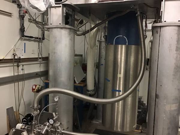
| 1700 | Borrowing a longer KF-25 hose from the Goldman lab, set up a pumping tee so that we can pump on IVC and/or CVJ. Pump out line. |
| 1700 | Start pumping out CVJ only. Turbo on CVJ = 4.6 ubar. (If we can get this down to 190 nbar like the IVC then maybe it will make sense to start pumping both out in parallel.) |
| 1710 | Turbo on CVJ = 2.2 ubar |
| 1715 | Valve out CVJ and switch back to pumping on IVC with Turbo. Turbo → 540 nbar. |
| 1720 | Valve out IVC and switch back to pumping on CVJ with Turbo. Turbo → 1.9 ubar. |
| 1725 | Turbo on CVJ = 1.4 ubar |
| 1730 | Valve out CVJ and switch back to pumping on IVC with Turbo. Turbo → 740 nbar. |
| 1730 | Open CVJ valve, now pumping on CVJ and IVC simultaneously. Turbo → 2.2 ubar. |
| 1746 | Pumping on CVJ and IVC simultaneously. Turbo → 1.2 ubar. |