| Status | Run 76 prep. All mixture in dump. LHe Trap and LN2 Traps pumped out. Cryostat Vacuum Jacket pumped out. Tower removed. |
| 1105 | Polish upper surface of adapter ring with ScotchBrite and clean with methanol. |
| 1130 | Examining accessory interposer. We want to use one connector pin that wasn't used in the last run: the far purple wire in the black/black/blank/purple/purple connector. But this is connected to SL 15 which is a QET bias line (we must have used it to ground an external electrode previously). Planning to resolder this to a redundant QET return pin (with socket removed). We will switch the far purple wire from Pin 15 to Pin 46 (which already has a black wire soldered to it). |
| 1150 | Polish bottom edge of 30 mK can with ScotchBrite. |
| 1215 | Finish modifying interposer. One black wire is now disconnected and dangling. |
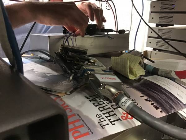
| 1215 | Planning diverter board on warm side. We'll use the “extra” one with no wires currently connected. We'll solder the connectors for the source controller directly to pins on the female side, also the two piezo wires. Can connect piezos to side plate on breakout box. |
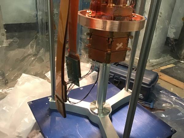
| 1445 | Bring Tower on stand into fridge clean tent. Put it on the scissor jack and center it below fridge. Raise tower stand ring and attach with three bolts to IVC bottom.
This is an opportunity to test source mover. Attach interposer to Stripline 41 and plug interposer connectors into proper places on Face 6 of tower. Stripline 1 connects to Cable 2 |
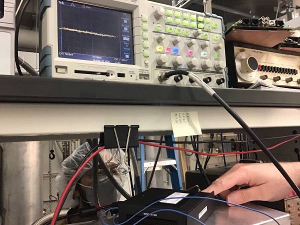
| 1455 | Connect Cable 2 to breakout box to check accessory wires. Y12/Y34/X12/X34 = 205.8/201/205.6/212.5. Check piezo wires with meter set to AC V - can see signal when we tap the tower. Connect piezo to scope - also see signal when we tap, though it seems to require a pretty hard tap. We'll finish wiring the diverter board, maybe it will be less noisy. |
| 1520 | Working on diverter board. We are using the “spare” diverter board. All the controller connectors are soldered on. Cut the end off a bnc cable to solder on for the piezo, this will connect directly to a scope. |
| 1545 | Connect new diverter board to Cable 2. Check new piezo connection, looks a little better. Plug diverter board into controller, connect controller to fridge laptop. Run Zero Both Axes.prg, then PZT calibration.prg to try to set the source mover to 0°/180°. Seems to be working. |
| 1600 | Having some trouble now seeing signals from the piezo, doesn't seem to be sensitive enough. |
| 1605 | Now doing PZT calibration but signal on scope is not good enough, instead someone is sitting near mover listening for clicks. Start with Zero Both Axes, then move X to -19 microsteps. Then move in -2 moves till it clicks. X-calibration verified by increments of 8 moves of -2 microsteps each, heard a tick on each 8th move. Completed process with X+21 microsteps which takes it to X=0. |
| 1610 | Working on Y-calibration now. After Zero Both Axes do Y+46. Then steps of +2. This is harder to hear. Verify with increment of 8 times +2 microsteps. Finish with Y-48 to set Y = 180°. |
| 1615 | Visually verify that it seems to be at the zero position: in one DIB slot can see the collimator approximately centered, in the opposite slot can see the hole at the end of the shaft approximately centered. |
| 1625 | Tried moving both X and Y, then moving back to center. Something went wrong here - looks like collimator wound up near center but shaft is way off. Hmm. |
| 1625 | Repeating calibration procedure…. rezeroed, everything seems to have worked. |
| 1650 | Did some tests moving X and Y in small moves, and watched through the slits to verify that it goes in the correct direction. It does indeed - so I guess we didn't mess up the wiring. |
| | Current situation: it seems that the motor is working properly, but the first test move should have worked. We moved to X=60/Y=60 which Scott knows is a “safe move” - we saw it move and it was fine as far as we could tell. But then he moved back to the default position X=0/Y=96, and it banged into something and wound up in some uncalibrated place. Need to assess what went wrong there. |
| 1715 | Unplug power supply for source mover controller. |