2020/02/13 (Thursday)
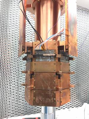
| 1410 | Threaded rods (brass M2) finally arrive. We also bought M2 brass nuts. Now we can finish stack assembly. |
|---|---|
| 1420 | Cut 5-inch lengths of M2 threaded rod and file the edges so that nuts go on easily. 5 inches seems just right for a 3-housing stack (housings for 1.3-inch high detectors) |
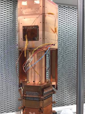
| 1440 | Assembled the 3-housing stack with the threaded rods and nuts. |
| 1450 | Put side coax ZB1-4-6 on DIB 4, ZB1-4-8 on DIB 1. Connected DIP 3 to tower face 2 using the side coax adapter. |
| 1500 | Connected the accessories to tower face 4. |
| 1535 | Tower electrical check, some problems. |
- DIB4 pC open - specifically Pin 5 open to everything, Pin 6 seems ok.
- DIB4 LED2 (pin 10) open
- Sporadic shorts were seen from phonon channels to chassis, but they disappeared.
| 1545 | Remove DIB4 side coax. DIB4pC problem seen at detector DIB. Open LED seen at side coax extender, but haven't checked yet in housing. |
|---|---|
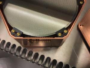
| 1605 | Disassemble stack and open G101D housing. DIB4 pin5 wirebond looks too short, no arc to it at all. Apparently it popped off at the detector bond pad. |
| 1610 | The LED problem seems to be simply that the solder joint from wire to side coax extender pin came loose. Resolder this connection. This resoldering was for pin 9 NOT pin 10. |
| 1640 | Turns out the LED was never soldered to pin 10, but pins 8 and 9 instead, resoldering the connection on pin 8 to pin 10. |
| 1700 | Rebond DIB4 pin5 in the wirebonder lab |
| 1725 | Reassemble stack, tighten threaded rods, reattach side coaxes and SCAB. Looks like LEDs and DIB4pC are OK. Note: to verify LEDs I had to connect to MC stage for chassis - maybe lower stages have high resistances to MC stage. |
| quick check shows 4K stage isolated, other 3 shorted together | |
| Ready to tape down wires and tape up holes. Then another electrical check. |
| Detector | G101D | DIB | 1 | ||
|---|---|---|---|---|---|
| side coax | ZB1-4-8 | date/who: | 2020 Feb 13 | DS, ZW, MF | |
| face | 3 | ||||
| +lead | - lead | signal | typical | previous | measured |
| 1 | 2 | QET A | 100 to 200 Ω | 213 Ω | |
| 2 | 4 | QETA-B | 100 to 200 Ω | 157 Ω | |
| 3 | 4 | QET B | 100 to 200 Ω | 136 Ω | |
| 4 | 6 | QETB-C | 100 to 200 Ω | 106 Ω | |
| 5 | 6 | QET C | 100 to 200 Ω | 153 Ω | |
| 6 | 8 | QETC-D | 100 to 200 Ω | Open | |
| 7 | 8 | QET D | 100 to 200 Ω | Open | |
| 2 | 8 | QETA-D | 100 to 200 Ω | Open | |
| chassis | 9 | LED1 Rforward | 8 to 9 MΩ | Open | |
| chassis | 9 | LED1 Vforward | 1.0 to 1.1 V | OL | |
| 9 | chassis | LED1 Rreverse | <1 nS | ||
| chassis | 10 | LED2 Vforward | 8 to 9 MΩ | Open | |
| chassis | 10 | LED2 Vforward | 1.0 to 1.1 V | OL | |
| 10 | chassis | LED2 Rreverse | <1 nS | ||
| 1 | 11 | Qo Rbias | 24 to 26 nS | ||
| 12 | 11 | Qo C coupling | <1 nS | ||
| 12 | 13 | Qo Rfeedback | 24 to 26 nS | ||
| 1 | 14 | Qi Rbias | 24 to 26 nS | ||
| 15 | 14 | Qi C coupling | <1 nS | ||
| 15 | 16 | Qi Rfeedback | 24 to 26 nS | ||
| All pins → Ground | all <1 nS | <1 nS | |||
| Detector | G101D | DIB | 3 | ||
|---|---|---|---|---|---|
| side coax | SCAB | date/who: | MF, DS, ZW | ||
| face | 2 | ||||
| +lead | - lead | signal | typical | previous | measured |
| 1 | 2 | QET A | 100 to 200 Ω | Open | |
| 2 | 4 | QETA-B | 100 to 200 Ω | Open | |
| 3 | 4 | QET B | 100 to 200 Ω | Open | |
| 4 | 6 | QETB-C | 100 to 200 Ω | Open | |
| 5 | 6 | QET C | 100 to 200 Ω | 94 Ω | |
| 6 | 8 | QETC-D | 100 to 200 Ω | Open | |
| 7 | 8 | QET D | 100 to 200 Ω | Open | |
| 2 | 8 | QETA-D | 100 to 200 Ω | Open | |
| chassis | 9 | LED1 Rforward | 8 to 9 MΩ | ||
| chassis | 9 | LED1 Vforward | 1.0 to 1.1 V | ||
| 9 | chassis | LED1 Rreverse | <1 nS | ||
| chassis | 10 | LED2 Rforward | 8 to 9 MΩ | ||
| chassis | 10 | LED2 Vforward | 1.0 to 1.1 V | ||
| 10 | chassis | LED2 Rreverse | <1 nS | ||
| 1 | 11 | Qo Rbias | 24 to 26 nS | ||
| 12 | 11 | Qo C coupling | <1 nS | ||
| 12 | 13 | Qo Rfeedback | 24 to 26 nS | ||
| 1 | 14 | Qi Rbias | 24 to 26 nS | ||
| 15 | 14 | Qi C coupling | <1 nS | ||
| 15 | 16 | Qi Rfeedback | 24 to 26 nS | ||
| All pins → Ground | all < 1 nS | < 1 nS | |||
| Checked pC to DIP 1 pA: 202 Ohms | |||||
| Detector | G101D | DIB | 4 | ||
|---|---|---|---|---|---|
| side coax | ZB1-4-6 | date/who: | MF, DS, ZW | ||
| face | 5 | ||||
| +lead | - lead | signal | typical | previous | measured |
| 1 | 2 | QET A | 100 to 200 Ω | Open | |
| 2 | 4 | QETA-B | 100 to 200 Ω | Open | |
| 3 | 4 | QET B | 100 to 200 Ω | Open | |
| 4 | 6 | QETB-C | 100 to 200 Ω | Open | |
| 5 | 6 | QET C | 100 to 200 Ω | Open | |
| 6 | 8 | QETC-D | 100 to 200 Ω | 200 Ω | |
| 7 | 8 | QET D | 100 to 200 Ω | 212 Ω | |
| 2 | 8 | QETA-D | 100 to 200 Ω | Open | |
| 9 | chassis | LED1 Rforward | 8 to 9 MΩ | 0.788 MΩ | |
| 9 | chassis | LED1 Vforward | 1.0 to 1.1 V | 1.086 V | |
| chassis | 9 | LED1 Rreverse | <1 nS | < 1 nS | |
| 10 | chassis | LED2 Rforward | 8 to 9 MΩ | .778 MΩ | |
| 10 | chassis | LED2 Vforward | 1.0 to 1.1 V | 1.086 V | |
| chassis | 10 | LED2 Rreverse | <1 nS | < 1 nS | |
| 1 | 11 | Qo Rbias | 24 to 26 nS | ||
| 12 | 11 | Qo C coupling | <1 nS | ||
| 12 | 13 | Qo Rfeedback | 24 to 26 nS | ||
| 1 | 14 | Qi Rbias | 24 to 26 nS | ||
| 15 | 14 | Qi C coupling | <1 nS | ||
| 15 | 16 | Qi Rfeedback | 24 to 26 nS | ||
| All pins → Ground | <0.1 nS | 5,6,7,8 short to chassis | |||
| Detector | G101D | DIB | Accessories | ||
|---|---|---|---|---|---|
| side coax | - | date/who: | 2020 Feb 13 | MF | |
| face | 4 | ||||
| +lead | - lead | signal | typical | previous | measured |
| 1 | 2 | Motor Coil A | 5-10 kΩ | 7.10 kΩ | 7.10 kΩ |
| 3 | 4 | Motor Coil B | 5-10 kΩ | 7.54 kΩ | 7.54 kΩ |
| 5 | chassis | Backward endstop - ground | open | open | open |
| 6 | chassis | Forward endstop - ground | open | open | open |
| 8 | 9 | Screw terminals | ~20 Ω | - | 69.9 Ω |
| 11 | 12 | Electrode | low Ω | - | 53.9 Ω |
| all pins | chassis | chassis isolation | <1 nS | - | <1 nS |