2019/10/04 (Friday)
| Status: Warmed up after leak seen from bath to IVC, Softened Vacuum Jacket , Tower removed. | |
| 0950 | Partially disassemble tower in clean room. Remove source housing and take out some of the source stepper assembly for modification. Put copper tape over LED holes in crown. |
| 1035 | Investigating source stepper failure. Took apart slide pot planning to remove a spacer to address sticking issues when cold. Found that a plastic component of the slider mechanism had shattered (right figure)! 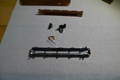 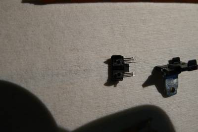 Unclear if this simply happened due to differential contraction, or rather it became stuck and trying to run the motor broke it off. If the latter, it is possible we had limited motion of the source carriage, but the sliding contact was stuck in place. |
| 1040 | Because we don't understand the cause of this failure, it may be safer to run without the slide potentiometer. We give up instant position feedback, but I don't see a simple solution that doesn't require constructing something like a custom slide pot ourselves. Because the slide pot served to keep the carriage from rotating on the drive shaft, we need to machine one more part to help serve a similar function. The designs for this piece are already complete. |
| 1717 | Completed the source stepper re-design. Made a new motor mounting plate than can hold a bar to keep the carriage from rotating. Instead of the slide pot, we've installed a conductive end stop at each end of the carriage's travel. These were made by soldering copper strips to some small PCBs which will then be connected to two of the wires formerly used for the slide pot. When the carriage is at either end of it's travel, it will make contact with the conductive stop and we can then measure a low resistance between the stop and GND. 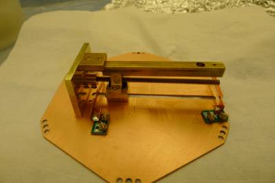 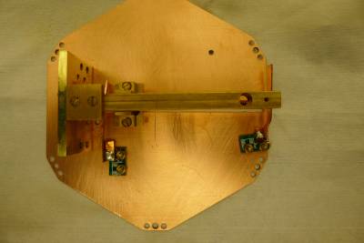 |
| 1740 | Re-attach stepper motor and solder wires to end stops. Blue wire is connected to near (low radius) end stop and blue-striped wire is connected to far (high radius) end stop. Green wire is left unconnected. |