2019/06/03 (Monday)
| Setup | DIB1/3/4 → 3.2 MHz filters 2/3/1 → cable 3/1/2 → gender changer ?/3/2 → HVConn 1/3/2 → HV 1/2 → DCRCX(4)/DCRC50(3) DCRC33(2) → 1kV power supply → HV input |
|---|---|
| 0000 | Tower = 49.2 mK |
| 0430 | MB = 77.1% |
| 0530 | MB = 75.7% |
| 0730 | MB = 72.9% |
| 0915 | Tower/MC/Coldplate = 48.6/31.1/177 mK, Still = 1.02 K / 0.095 mbar, G1/G2 = 189/175 mbar, 1K Pot = 1.63 K / 22 mbar. MB = 70.5% coldplate and still are reading in their “low” modes for whatever reason |
| Tower temperature continues to fall linearly, slowly | |
| 0925 | Fill LN2 Cold trap bath |
| 0937 | Start a series at HV = 0V, after 5 min dial up to -125V. After 40 min dial back down to 0V. CDMS detector: Driver Gains = 1x, DCRC4/3 QET biases = (420/370/440)/(420/400/450) uA, Front-End Gains = (2/2/3)/(5/5/5) 1000 BOR randoms, 10 Hz in-run randoms, trigger on DCRC4pA/B/C threshold = 7/7/7 |
| 0945 | After applying -125V bias, Vtest is only 0.05 mV. In fact if there were significant leakage, this would be negative, so it's probably essentially 0. |
| 1025 | Dial HV back to 0V |
| 1145 | Stop data. |
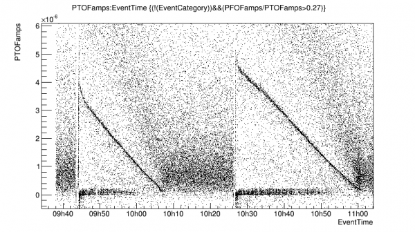
- Based on the apparent Luke gain the initial max effective detector bias is around 88.8 V
- The effective detector bias right after the HV is removed is higher: 102.6 V.
- The noise in absolute units is flat at around 830 eVt
- (all the above are based on the amplitude of the 60keV line at 0 V measured a few days ago, seems to be consistent with this data)
- To cancel the counter bias we should drift the applied bias up at a rate of around 3.9 V/min.
| 1215 | MB = 66.1% |
|---|---|
| 1400 | Set up remote HV using DCRC2. HV max set to 441.4 |
| 1415 | Set up calibration for remote HV control here: HV_DCRC2_control_cals_440V_190603.txt |
| 1415 | MB = 63.2% |
| 1500 | Performed a HV test from 0 - 440 V |
| HV(V) | Vtest(mV) | DCRC4pA base (V) | Notes |
|---|---|---|---|
| 0.1 | 0.03 | -1.18 | |
| 20 | 0.04 | -1.11 | |
| 50 | 0.04 | -1.11 | Noise gets worse on change then settles |
| 104 | 0.04 | -1.08 | |
| 150 | 0.04 | -1.08 | |
| 204 | 0.04 | -1.08 | |
| 250 | 0.04 | -1.04 | |
| 303 | 0.04 | -1.08 | Waited a minute longer, base line decreased a bit |
| 350 | 0.04 | -1.03 | |
| 403 | 0.04 | -1.01 | |
| 441 | 0.04 | -.97 | Noise gets worse on change then settles |
| 1550 | Use the python code to generate a sequence to drift the bias from 300 to 400 V at 3.9 V/min: |
|---|
python HVscan.py -iDCRC 2 -HVs 300 -HVcalFile HV_calibrations/HV_DCRC2_control_cals_440V_190603.txt -HVdriftRate 0.065 -HVpreBias 5/1 -tSeries 25 -DCRCs2Flash 3,4 > ../../sequencer/HVdrift_300V_3p9VPM_prebias_5_1_dur_25min.msl
| 1621 | Start a 25 min series at HV = 300→400V, rate +3.9V/min with 5% prebias for 1 minute, flash at end with 30 min wait. CDMS detector: Driver Gains = 1x, DCRC4/3 QET biases = (420/370/440)/(420/400/450) uA, Front-End Gains = (2/2/3)/(5/5/5) 1000 BOR randoms, 10 Hz in-run randoms, trigger on DCRC4pA/B/C threshold = 6/6/6. Use sequence HVdrift_300V_3p9VPM_prebias_5_1_dur_25min.msl |
|---|---|
| 1635 | Data has started. All channels look OK. Leakage voltage is much higher than before! Looks like it rose to about 50 mV during the ramp up, stayed around there during data taking, and fell to close to 0 during the rampdown. This would reduce the applied bias from 300V to ~280V. |
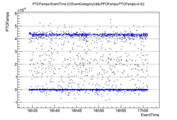 |  |
- Plot on left shows we got the drift rate just right.
- Plot on left is high pF partition. The clear line is 60 keV, but it's very saturated.
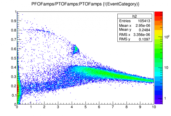
- Plot on right just barely shows lower Am lines. Can do standard quadratic fit on 14 and 18 keV lines.
With the quadratic calibration, noise sigma is 17.4 eVee. That's pretty good!- With the quadratic calibration, noise sigma is 37 eVee. Previously I thought it was 17.4 eVee but I misidentified the 14keV and 18keV lines.
- (note that a linear calibration from the 14 keV line implies noise sigma of 50 eVee, which would not be so good.)
| 1635 | Tower = 48.3 mK |
|---|---|
| 1615 | MB = 60.3% |
| 1645 | Fill LN2 Cold trap bath |
| 1715 | MB = 58.9% |
| 1815 | MB = 57.4% |
| 2015 | MB = 53.0% |