2019/04/23 (Tuesday)
| Status | Room temperature. All mixture in dump. LN2 traps, 4He trap, fridge all pumped out. 1K Pot needle valve closed. Cryostat vacuum jacket pumped out. Tower installation begun. SQUETs ready. Still need to finish SQUET/stripline diverter board to reroute HV wiring. |
|---|---|
| Installation plan: |
| G101C DIB | 1 | 3 | 4 |
|---|---|---|---|
| Tower IT4 Face | #5 | #3 | #1 |
| Side Coax | ST-3-3 | ST-3-8 | ST-3-10 |
| Orientation | E | SW | NW |
| SQUET | ZC-68 | ZC-13 | ZC-26 |
| Stripline | #43 | #41 | #48 |
| Cable | 3 | 1 | 2 |
| HV Interposer | |
|---|---|
| Construct SQUET-end interposer board with modifications to divert 2 HV biased lines to another tower face. This was constructed using a blank SQUET-end interposer/breakout board that we found in the cabinet. It was probably an early version of the smaller interposer boards that were eventually used to accommodate stripline breakages. The pin layout for this interposer is described here: interposer_breakout_wiring.xls. To achieve the correct gap, we needed to order Mill-Max pins with the proper length (0.45“). These are Mill-Max part number: 0461-1-15-15-11-27-04-0. | |
| To divert HV before it reaches the SQUET, we broke off sockets 2 and 15 (PA QET/ret) and connected wires with Mill-Max pins to the appropriate breakout connectors. The HV board was similarly modified to provide bias to only these two lines as documented on the hv board page. | |
| 1205 | 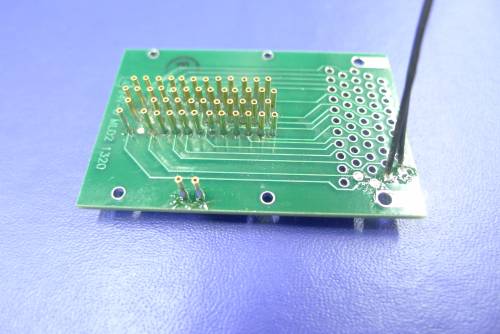 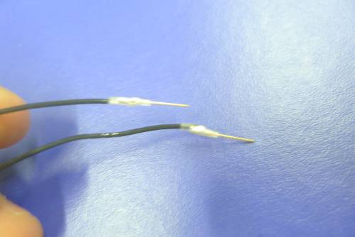 |
| 1210 | 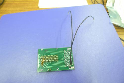 |
| Tower installation | |
|---|---|
| 1255 | Tower installation is complete to the 4K stage. Replaced the standard 4K shield and heatsinks which were left off last run. First polished the copper contact surfaces with ScotchBrite. |
| 1325 | Attach diverter (interposer) board to Stripline #48 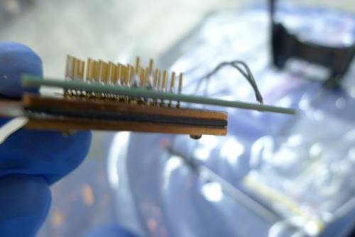 [image not archived: p1020095.jpg] |
| 1330 | Attach SQUET ZC-26 to diverter board 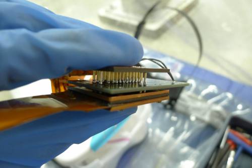 |
| 1340 | The flyover cable on ZC-26 is in sharp contact with the edge of the copper stripline end board. In the past this sort of thing produced shorts… 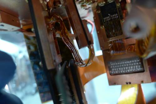 |
| 1345 | Decided to attach the SQUID card to the next position over on the 600 mK ring. This avoids the flyover cable contacting the stripline board, and it doesn't seem to put excess tension/torsion on the flyover cable. 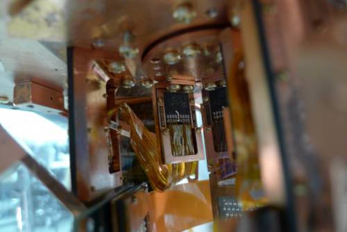 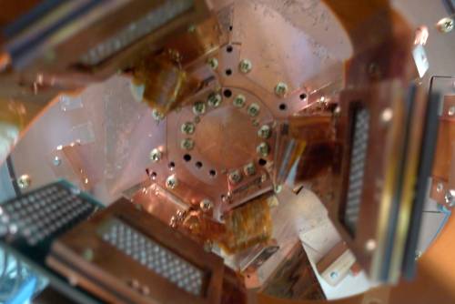 |
| 1355 | Plug wires from diverter board into Tower Face 2 pins 1&2. 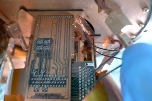 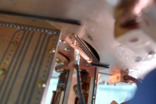 I considered whether we need something to hold these pins in. The tension of the wires seems to be such that there's a bit of sideways force on the pins, so it seems like this is likely to hold them up. So leaving it as is, we'll try it. |
| 1520 | Finish electrical checkouts on all 3 DIBs. Looks good. Notes: |
- DIB1 pD SQUID and Feedback are open - we knew this. Not a readout channel.
- DIB4 pA Feedback has low resistance. Known problem with this SQUET. Not a readout channel.
- DIB4 pA QET to QET Return 1 is 120 Ω. This is the HV channel. Should be about 60 Ω for the tower wires, 60 Ω for the stripline, so this is about right. The other four returns read open as they should (only one of them is diverted to HV).
| 1615 | Partially attach IVC bottom, then quick electrical check of phonon and HV components - all ok. |
|---|---|
| 1625 | Start slowly pumping out IVC with scroll pump while continuing to tighten screws |
| 1640 | Scroll pump on IVC = 160 μbar |
| 1650 | Pressure not quite low enough to switch to turbo. Stop pumping on IVC, we'll pump more tomorrow. |
| 1650 | IVC = 340 μbar |