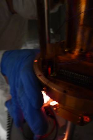
| Tower assembly |
| 0940 | Clean the modified tower crown in warm water in the ultrasonic cleaner for 15 minutes |
| 1000 | Find some short 0-80 screws to mount the LEDs |
| 1010 | Polish the thermal contact surfaces on the modified tower crown. Also on the tower connector tube. |
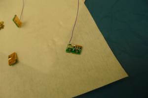
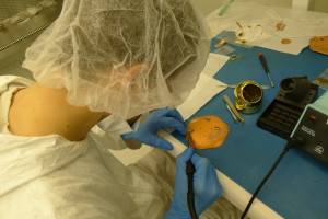
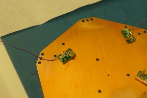
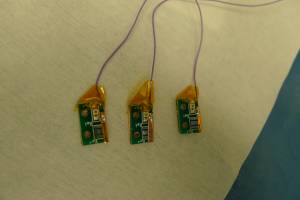
| 1020 | Resolder wires to LED boards, so they lay flat and point the right way so we can attach them face down on the crown without shorting the connection. Also cover them with kapton to help prevent shorts.
  |
| 1035 | Cover outermost holes on tower crown with copper tape. These are the holes for when you screw the crown to a housing. These had been left open the last few runs. |
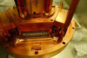
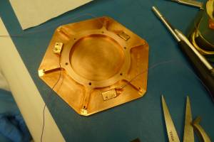
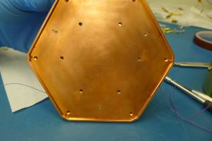
| 1045 | Mount LEDs on crown. Check electrical connection with meter in diode mode - two look good showing proper voltages, one however is shorted to chassis. Seems that a little sharp point of solder cut through the kapton. Replace the piece of kapton and add a second layer. Now they all look good.
  |
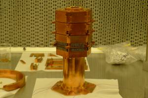
| 1320 | Attach crown with LEDs to tower.
 |
| 1330 | Remove G101c from the source safe, where it has been activating, and move it into cleanroom. |
| 1340 | Perform electrical checkout on G101c: same as two days ago. Only 6 channels show continuity which makes sense, all Side2 has been disconnected. Also checked some cross-channel resistances: around 100 Ω. Can use this to assure no continuity between electrode and detector. |
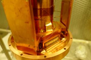
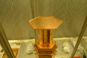
| 1350 | Mount detector on tower, DIBs 1/3/4 → IT4 Tower Faces 5/3/1. The 3 crown LEDs are on the same sides as the DIBs.
 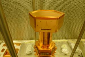 |
| 1420 | Mount electrode housing on the tower. Slot for the electrode wire is above DIB4 - we'll connect to DIB4's QETA and QETA return, this is an unused channel (disconnected from Side 2). Check for leakage between electrode and one of the phonon channels: 0.1 nS. (Before putting the electrode on I checked continuity between crystal edge and a phonon channel and got around 200 Ω.
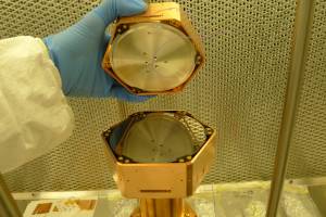 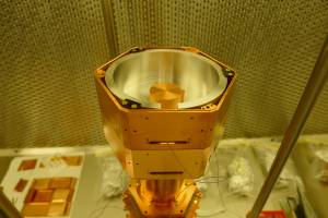 |
| 1430 | Cover outermost holes of stack lid with copper tape. Another thing we usually neglect. |
| 1445 | Attach threaded rods to stack, with tower thermometer mounted on top of the stack.
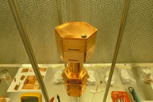 |
| 1455 | Check again for leakage between electrode and housing or crystal: both less than 0.2 nS |
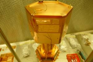
| 1500 | Cover all stack holes with copper tape. This is essentially unused DIB slots and the screw holes for them. Note that the holes near the corners don't have to be covered because they aren't open to the interior (they are there for pumpout of the screw holes at top and bottom). On one DIB screw hole left a little “tent” to maybe help prevent trapped air during pumpout.
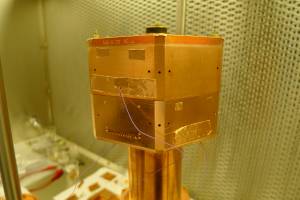  |
| 1520 | While laying tower on its side accidentally bent, then broke off, DIB socket on DIB3 for qI (pin 12). Luckily this is not used. Need to be more careful. |
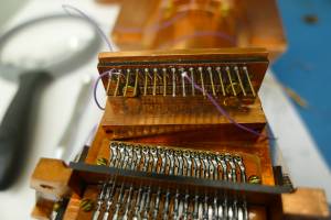
| 1535 | Solder two of the LED wires to side coax extender Pins 9&10 and plug in below DIB1 |
| 1540 | Solder the electrode wire to Pins 1&2 (QET A and Return) of another side coax extender. Also solder the third LED to Pin 9 of this extender. Plug in below DIB4.
 |
| 1555 | Attach side coaxes, ST-3-3/ST-3-8/ST-3-10 → DIBs 1/3/4. Leave off screws on the detector side. |
| 1610 | Tower electrical check: |