2019/02/04 (Monday)
| 1440 | Plug DCRC1(55) into the minibob and power up. Telnet to DCRC1 and view power supply voltages, etc. with MO 1 command. These seem reasonable. Guessing the Negative voltage displays are just missing the correct sign here? |
|---|
MO 1
TempC    = 31.0
Adc_5.0v =  5.06v  (adc_Ch15) 850 *  5.95mV/bit
Vcc_3.3v =  3.33v  (adc_Ch04) 556 *  5.99mV/bit
Vcc_1.8v =  1.83v  (adc_Ch05) 610 *  3.00mV/bit
Vcc_3.3v =  3.32v  (adc_Ch04) 554 *  5.99mV/bit
FetT     =  0.46v  (adc_Ch02)  85 *  5.40mV/bit
Pos_15v  = 15.42v  (adc_Ch00) 803 * 19.20mV/bit
Neg_5.0v =  5.06v  (adc_Ch14) 850 *  5.95mV/bit
Pos_5.0v =  5.41v  (adc_Ch07) 564 *  9.60mV/bit
Neg_15v  = 15.13v  (adc_Ch01) 824 * 18.36mV/bit
Zap_Mon  =  0.00v  (adc_Ch03)   0 *  5.40mV/bit
| 1500 | Start up MIDAS. Disable logging, disable all but DCRC1. Start up a vnc and the SQUIDtuningGUI on cdms2. Start dcrc odb programs. Start a run with only 5Hz random triggering. Can see charge traces, but phonons are railed. |
|---|---|
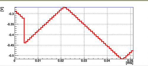
| 1515 | Change PA to open loop polarity (feedback disabled). Turn on test signal (DDSControlReg=3543), set frequency to 20kHz. Connect test signal to PA and connect PA ADC to preamp. Shorten DCRC1 phonon traces to 64 bins (PhononWaveFormLength=128 in the MIDAS DAQ settings) With this setup, we can see the test signal in the SQUID tuning gui. Immediately we observe the first 8-bin glitch occurring, example below. Observe that the glitch isn't always present, but when it is, it is always ≤ the first 8 bins. Also, the glitchy bins still seem to have the right test signal shape, so are not random garbage. |
| PA test signal glitch |
|---|
 |
| 1540 | Change to triggering on the dcrc test signal. Set up PB in the same manner as PA. Also observe first 8 bin glitch in PB, though it seems less frequent. Set up channels C and D as well. For each channel, observe 100 traces and count obvious first-8 bin glitches. During this time, the signal in all channels remains synchronized with trigger (i.e. no shifting of one channel relative to the other), and the rest of the signal looked fine (no 8-wise shifting) |
|---|
| DCRC1(55) | |
|---|---|
| Channel | # glitches out of 100 |
| PA | 46 |
| PB | 9 |
| PC | 12 |
| PD | 10 |
| 1600 | The current run has been going for 25 min without any of the other glitches showing up. Let's try adding another DCRC to the mix. DCRC3(50) is still attached to the (warm) detector and readout hardware, so I think it won't hurt it to power it up like that since it's still got FETs down there. Stop MIDAS run, stop MIDAS programs. Power down DCRC1. Daisy chain DCRC1 and DCRC3 with DCRC1 as master. Power on DCRC1 then DCRC3. DCRC3 voltages look fine. |
|---|
MO 1
TempC    = 17.0
Adc_5.0v =  5.03v  (adc_Ch15) 845 *  5.95mV/bit
Vcc_3.3v =  3.34v  (adc_Ch04) 557 *  5.99mV/bit
Vcc_1.8v =  1.84v  (adc_Ch05) 612 *  3.00mV/bit
Vcc_3.3v =  3.33v  (adc_Ch04) 556 *  5.99mV/bit
FetT     =  4.81v  (adc_Ch02) 890 *  5.40mV/bit
Pos_15v  = 17.49v  (adc_Ch00) 911 * 19.20mV/bit
Neg_5.0v =  5.03v  (adc_Ch14) 845 *  5.95mV/bit
Pos_5.0v =  5.44v  (adc_Ch07) 567 *  9.60mV/bit
Neg_15v  = 14.89v  (adc_Ch01) 811 * 18.36mV/bit
Zap_Mon  =  0.00v  (adc_Ch03)   0 *  4.75mV/bit
| 1605 | Set up DCRC3 phonon channels as above. (64 bin trace length, 0 driver offset, test signal connected and ADC connected to preamp) Set up test signal as on DCRC1. DCRC1 phonon channels show test signal as before, and DCRC3 charge channels are reading out noise, but DCRC3 phonon channels remain railed low (-1.25 V). |
|---|---|
| 1615 | Strange, I can see the test signal on DCRC3 channels when connecting the ADC to the feedback amp, but not the preamp. Well, let's go ahead with that setup. Again easily observe the first-8 bin glitch on all DCRC3 channels, most frequently on PA. |
| DCRC3(50) | |
|---|---|
| Channel | # glitches out of 100 |
| PA | 36 |
| PB | 4 |
| PC | 8 |
| PD | 6 |
| 1430 | Change to trigger on DCRC3 phonon thresholds with all thresholds at 15ADC. In the previous detector run, we were triggering on 3 of these same channels. Still see first 8 bin glitches, all channels are out of phase with the trigger now since it's pretty much constantly triggering. Impossible to tell if they are in phase with each other with this pulse viewer. |
|---|---|
| 1435 | Change phonon trace lengths to 512 samples to look for glitches later in the trace. Nothing obvious seen. |
| 1640 | Power down DCRCs. Daisy chain in DCRC2(33), which is connected to our bias voltage control board and DCRCX, which is connected to the NaI outputs. Turn on all 4 DCRCs. Enable DCRCs2,4 in the MIDAS ODB. Start up MIDAS DCRC programs and start a run. Can again see test signal in DCRCs 1,3. First 8 bin glitch is present, but otherwise things look fine. |
| 1656 | Change trace lengths back to 4096 samples (3.2768 ms) and reduce test signal rate to 5kHz. Let's try saving data like we do during a run. Stop the run and close the pulse viewer. |
| 1658 | Start test data series with 1000 initial randoms at 20Hz and DCRC3 phonon triggers =(15/15/15/15). DCRC1,3 phonons connected to 5kHz test signals at the preamp(DCRC1) and the feedback amp(DCRC3). |
| 1705 | Using BatViewer to look at saved data, the test signal channels all appear synchronized and the only apparent glitch is the first-8 glitch. |
| 1708 | Stop data after 10 min. Let's let the DCRCs run overnight like this and see if things are worse in the morning. Disable data logging, but start a new run. |
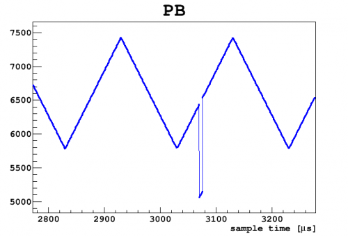
| 1710 | Randomly looking at saved data, saw a glitch of some sort in DCRC1 PB starting around event 100112 of this test series(07190204_1658). See image below, it appears in a number of subsequent events. We've observed such things in the r68 data and removed them with a fall time cut. It may be worth writing some code to process this test series and search for glitches. |
 |