2018/04/02 (Monday)
| Setup: DIB1/2 → SL 43/41 → 3.2 MHz filters → cables 3/1 → DCRC50(3)/55(1). | |
| Overnight: Flash and take a set of 8V Ba series. | |
| 0942 | Tower/MC/Coldplate = 39.7/36.2/202 mK, Still = 1.35 K / 0.055 mbar, G1/G2 = 123/117 mbar, 1K Pot = 1.45 K /5.5 mbar. Main bath = 37.4% |
| 0947 | Tweak 1K pot open a bit more. 1K Pot → 1.62 K / 27 mbar |
| 0948 | Fill LN2 cold trap full. |
| 0950 | Return 133Ba source to safe. |
| 1000 | Open V14 to put remaining mixture back into circulation. Since the fridge failure Saturday morning, we've been running warm at base, and still pressure is low. Hopefully this just means we still need to get the rest of the mixture into circulation. |
| 1016 | Stop programs and power down DCRCs. Install DSub switchboard between DCRC3 and detector cable. Connect Agilent 33521A function generator across bias electrode (QETD ret) and ground, include 100x attenuation between function generator and switchboard. |
| 1017 | Start DCRC programs. Set function generator to 10Hz square wave with 50mVpp setting ⇒ 500uVpp at bias electrode. View pulses using SQUIDtuningGUI. Seems to be in the bad trigger mode. |
| 1027 | Restart the run and triggering is okay. Channels are much noisier now though, so trigger levels are around 250ADC to get out of the baseline noise. Not sure if we'll be able to do this calibration down to the ~60keV level with this noise. |
| 1035 | Still = 0.34 mbar. Close V14, most mix now out of dump. Condenser falls to 0.055 mbar, still very low |
| 1043 | Play around with function generator connections. Find that plugging it into the instrument (orange) wall outlet with the cheater extension cord (ground disconnected) and placing the function generator on the ground behind the DAQ desk reduces the noise so I can set the trigger level to ~150 ADC. |
| 1058 | Start test signal calibration series with 10Hz, square wave signal on bias electrode, triggering on DCRC1QI = 150 ADC bins, 1000 initial randoms, DCRC bias = 0V. Change the test signal amplitude every 5 mins. Bias electrode amplitudes are (70 uVpp, 100 uVpp, 200 uVpp, 500 uVpp, 1 mVpp, 5mVpp) Triggering looks good above 100uVpp. |
| 1134 | Enable DCRC4, connect DCRC4 LED line to function generator trigger output. Connect DCRC4 LED voltage to phonon ADCs. Start up programs. Using pulse viewer, can see that we're able to trigger on the function generator trigger rising edge. However, this only gives us the upright charge pulses, since we're only triggering at the start of each full square waveform. I can, however change the output phase to align the other polarity with the trigger pulse. So I'll just have to scan through both polarities as well as amplitudes this way. |
| 1142 | Start test signal calibration series with 10Hz, square wave signal on bias electrode, triggering on DCRC4PA (function generator sync)= 100 ADC bins, 1000 initial randoms, DCRC bias = 0V. Change the test signal phase every 3 mins, and amplitude every 6 min. Bias electrode amplitudes are (10 uVpp, 25 uVpp, 50 uVpp, 100 uVpp, 500 uVpp, 1 mVpp) |
| 1220 | Stop dcrc programs and power down dcrcs. Remove Dsub switchboard. Since the DCRCs are powered down, try also removing the Pi filters. Start up DCRCs. We still have the 2 high frequency (~400kHz) noise peaks in charge channels. The filters don't seem to have changed anything qualitatively. Power down dcrcs. |
| 1230 | Replace Pi filters. Power up just DCRC1. It has a single noise peak. Power down dcrcs. |
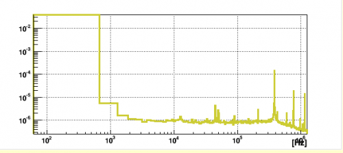 |
| DCRC1 with Pi filter and detector cable |
| 1237 | Attach dcrc1 to pi filter at ebox. i.e. remove the long detector cable. Power up dcrc1. Noise may be a little better, but is still dominated by the ~400kHz oscillation. |
|---|
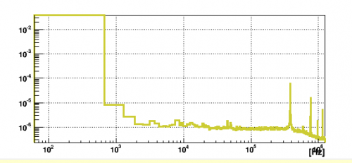 |
| DCRC1 with Pi filter but no detector cable |
| 1240 | Attach DCRC1 to miniBob. Noise is quite different. |
|---|
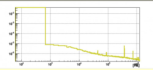 |
| DCRC1 on miniBob |
| 1245 | With DCRC1 on minibob, power on DCRC3 on DIB1 with timing link attached. You can see a little bit of DCRC3's noise in DCRC1. There's not much of DCRC1's noise in DCRC3 though. |
|---|
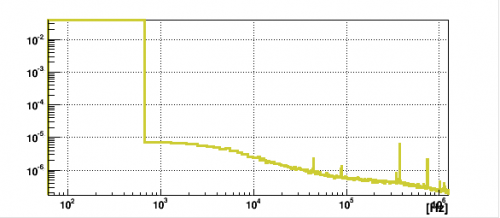 |
| DCRC1 on miniBob with DCRC3 powered on |
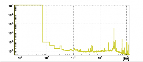 |
| DCRC3 with DCRC1 on miniBob. |
| 1258 | Put DCRCs back in “standard” setup. Setup: DIB1/2 → SL 43/41 → 3.2 MHz filters → cables 3/1 → DCRC50(3)/55(1). |
|---|
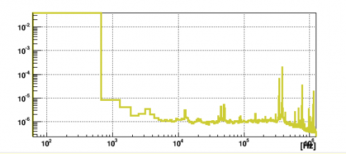 |
| DCRC1 in standard mode |
| 1303 | Turning off DCRC3 15V power seems to have no effect on the noise peaks seen in DCRC1. |
|---|
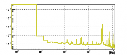 |
| DCRC1 with DCRC3 15V power off. |
| 1305 | Turn DCRC3 15V power back on |
|---|---|
| We saw some indications that grounding the detector after being biased for a while will then give pulses of opposite polarity. This may indicate some counter bias is developing. Let's try to take some more of that type of data. | |
| 1309 | Start series of data with DCRC bias = 0 V, 1000 beginning randoms, and a 60/50/70/50 bin threshold trigger on DCRC1qI/qO/DCRC3qI/qO, with 1.6384 ms pulses (8192 length) and 400 us prepulse (500 length). Noise triggers. |
| 1314 | DCRC LEDs indicate DCRC3 is constantly triggering stop run Let's just restart it since that seems to work sometimes. |
| 1315 | Start series of data with DCRC bias = 0 V, 1000 beginning randoms, and a 60/50/70/50 bin threshold trigger on DCRC1qI/qO/DCRC3qI/qO, with 1.6384 ms pulses (8192 length) and 400 us prepulse (500 length). Good triggering. |
| 1330 | Set DCRC bias = 8V using set_dcrc_bias.msl |
| 1345 | Set DCRC bias = 0V using set_dcrc_bias.msl |
| 1350 | DCRC LEDs indicate we're still getting a decent rate of events. |
| 1422 | The dump file size seems to be a good proxy for event rate. In the first 15 min it was around 2Meg, after applying the 8V bias, it was 200Meg, after grounding the detector, it has fallen steadily to plateau ~10Meg. Stop the run |
| 1425 | Flash detector for 30s |
| 1457 | Start series of data with DCRC bias = 0 V, 1000 beginning randoms, and a 60/50/70/50 bin threshold trigger on DCRC1qI/qO/DCRC3qI/qO, with 1.6384 ms pulses (8192 length) and 400 us prepulse (500 length). Good triggering. |
| 1512 | Set DCRC bias = -8V using set_dcrc_bias.msl |
| 1533 | Set DCRC bias = 0V using set_dcrc_bias.msl |
| 1608 | Dump sizes have fallen, stop the run |
| 1610 | Experiment with still heating to see if we can improve base temperature by increasing circulation pressures. Applying 2 mW to still heater causes significant decrease in base temperature. |
| 1620 | Still 2 mW / 0.055→0.090 mbar, Condenser 125→160 mbar (rising), Tower 39.5→34.9 mbar (flattening) |
| 1630 | Still 2 mW / 0.090 mbar, Condenser 163 mbar (flattening), Tower 35.0 mbar |
| 1630 | Try raising still heater to 4 mW. Another drop in base temperature. |
| 1640 | Still 4 mW / 0.120 mbar, Condenser 189 mbar (rising), Tower 33.5 mbar (flattening) |
| Start warmup | |
| 1645 | Turn off still heater |
| 1645 | Close V6 to stop circulation and allow mix to expand into still line |
| 1650 | Towr → 150 mK. Condenser pressure falling, Still pressure rising. |
| 1650 | Pump mix out of Trap 1: Close V13a to close inlet to trap, close V1 to isolate condenser. Open V9 to open pump outlet to dump. Open V5 to pump out Trap 1. Check Trap 2 as well just in case - pump a couple mbar out of Trap 2 to dump. |
| 1700 | Isolate Trap 1/2 and 3He pump: close V12a/b to isolate Trap 1/2, close V5 to stop pumping on lines, close V9 to isolate 3He pump from dump. |
| 1700 | Turn off 3He pump. |
| 1705 | Open Condenser to Dump by opening V1 and V4. Open Still to Dump by opening V14 |
| 1705 | Condenser (G1) = 21.5 mbar, Still (P1) = 34 mbar, Tower = 360 mK |
| 1705 | Close 1K Pot speedivalve to stop pumping on pot. Leaving needle valve open. Close V4a and valve to 4He pump. Open 4He outlet to “exhaust” and close recovery valve. Turn off 4He pump. |
| 1705 | Tower = 436 mK. Leaving the tower thermometer on with range reduced to 6.32 kΩ and excitation left at 6.32 uV |
| 1710 | Tower/1K Pot = 0.467/2.14 K, both rising |