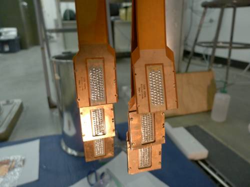
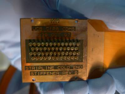
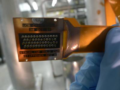
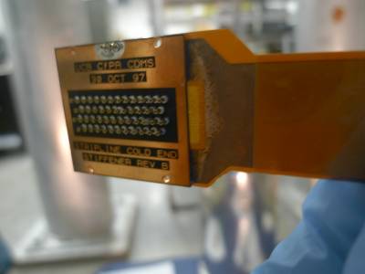
| | The CDMS cold hardware website has a stripline document showing that at some point epoxy was added to the space between the PCB fillet and the stripline surface in order to support weak connections. Our old striplines didn't have this - the new ones do. |
| | Since our setup involves twisting the striplines at the cold end, we will try a little more support - add some strips of Kapton tape to the area where the stripline meets the end clamp (on the stripline side, as opposed to the pcb side). These would go partially under the clamp and lend a little extra stiffness, so that less of the twist would occur right at the end. Additionally we can perhaps put some tape over the edge of the clamp onto the stripline after putting the clamps back on. (What we typically call protector plates are called clamps in the cold hardware documentation.) |
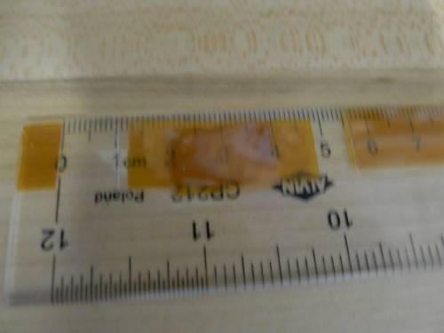
| 1140 | In the middle of where I want to put the tape, there's a rectangle where the wires are visible, and according to the documentation they are covered with epoxy. I don't want to put adhesive on top of this, because if we decide to remove it we might pull off the epoxy. So I made “band-aids” of tape - a 2 cm piece taped to the 3.5 cm strip, sticky sides together.
 |
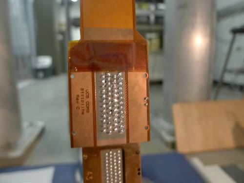
| 1145 | Along with the first “band-aid” piece, apply two additional 3.5 cm strips.
 |
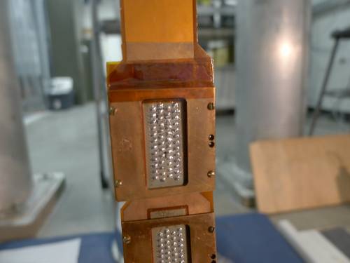
| 1150 | Replace clamps. Clamp overlaps the tape on the stripline. One more 3.5 cm piece of tape over the joint between clamp and stripline. (This will need to be peeled off when we want to take the clamps off again.)
 |
| 1215 | Repeat above for the other two striplines. |
| 1300 | Measured the hang length of the striplines. According to dimensions in my fridge spreadsheet, the bottom of the 600 mK rod is 3.5 inches above the bottom of the lower stripline heatsink. Using this we estimated that the shortest stripline would only be 10.5 inches between heatsink and connector. This feels a little harsh for the required fold+twist+loop, so we raised the upper heatsink closer to the bottom baffle, so instead of 2 inches apart they are now about 0.5 inches apart. Now the shortest stripline is about 12 inches between heatsink and connector. |
| 1410 | Polish the outer surface of the lower 100mK shield. |
| 1430 | Perform a quick continuity check on the stripline wires by plugging the Dsub50 shorting plug into the Ebox connectors, then measuring continuity on the cold end connector between a ground socket and each of the 50 other sockets. All wires on all three striplines look good. |
| 1610 | Install lower 100mK shield. First polished the contact surfaces at the bottom of the upper can and top of the lower can. |
| 1645 | Install MC connector spool. First polished the contact surfaces at the bottom of the MC and the top and bottom of the spool. |