2017/06/21 (Wednesday)
| Status | Tower removed from fridge. Mixture has been cryocleaned 3 times. Fridge is evacuated but should probably be pumped out again. 1K Pot needle valve is open, so now there will be air in the pot, should pump it out before cooling. Cryostat vacuum jacket has been pumped down to 190 ubar, maybe should be pumped out more before cooling. |
|---|---|
| 0905 | Lab = 22.6 C, 41% humidity. |
To do:
- Set up sources: plan is to use Pb and Am
- decide whether position of Am on Pb source holder is acceptable, either offset or centered
- drill hole in Pb source holder plate to allow LED light through
- offset Am source holder needs to be modified for 150mm setup so we don't want to use it this run… so drill center hole for Am in Pb source holder plate
- Electrical checkout for charge channels on striplines - could do now or wait for install
- Assemble source/LED housing, tower. All contacts from tower to adapter to MC can should be polished.
Using the mask figures found on the Confluence 4" MIT iZIP page (which is the iZIPv7 design) and Hassan's design for the Pb source holder I made the figure below showing the possible source positions:
| Possible positions of sources if Pb and Am are used |
|---|
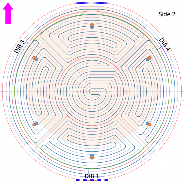 |
| Sources point at Side 2. Blue circles show positions of Am source if offset is used Orange circles show positions of Am source if centered source holder used Shaded region shows one possible position of Pb source Red lines indicate phonon channel regions Green circle indicates qOuter/qInner border |
| 1146 | Remove Pb from source holder. Take Pb source plate to shop for machining. |
|---|---|
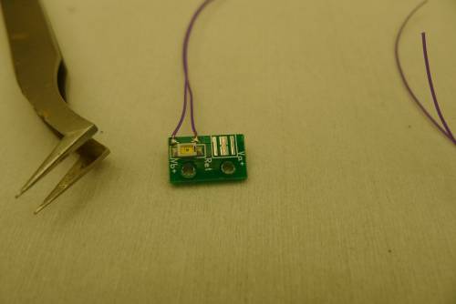
| 1200 | Mount 1650nm LED from Queen's on external LED board. It just barely fits the pads designed for the IR LED. Seems to be connected properly with Vforward = 0.600V. |
| 1650nm LED mounted on board |
|---|
 |
| 1215 | Drilled a 0.04“ hole in the Pb source plate centered (approximately) in the Am source mounting holes. Also drilled a 0.375” hole to allow LED light through. |
|---|---|
| 1227 | Return Pb source plate to clean room, install Pb source on souce plate. |
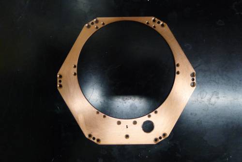
| 1245 | Mount Pb source and Am source (centered collimator) on Pb source plate. New Am hole in plate is not quite centered but the collimator hole is not blocked so it's probably OK. note this is one of our old 1 uCi Am sources (the smaller pellet-shaped ones) which should have a much higher rate than the smoke-detector source used in the last run. |
|---|
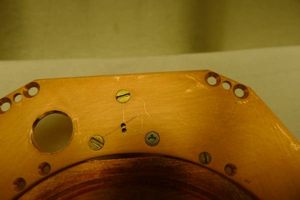 |
| Zooming in you can see that the collimator hole is a little off-center in the hole through the copper plate. |
Plan for tower construction:
- Pb and Am sources
- Am source situated opposite to DIB1. This places it at the centerline of Side2 pD. This puts the hole for LED light on the other side from the built-in LEDs on DIB1.
- Tower face and side-coax orientations probably not important. Maybe just line up lowest-numbered with lowest-numbered.
| 1450 | Remove tower and G132 from purge |
|---|---|
| 1455 | Put detector on tower. Holding it in place temporarily with two crown screws, lid still on the top. DIBs 1/3/4 are situated at Tower Faces 1/5/3. |
| 1500 | Modified long-wavelength LED board, added a ground sheet that wraps around the bottom like the other ones. |
| 1515 | Assemble source/LED/thermometer housing, three 940 nm LEDs and one 1650 nm LED: |
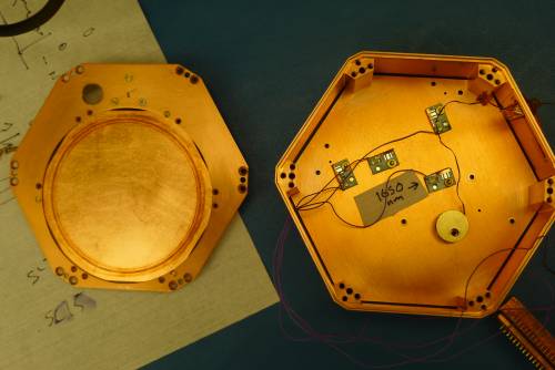 |
| Bottom in this photo is DIB1 position. Source faces Side 2 of detector. |
| 1550 | Assemble stack: detector then source housing then lid, held together with 5 threaded rods. Scotch-brite bottom of 50mK tower ears. Scotch-brite adapter ring, both the surfaces that attach to the tower ears and the surface that attaches to the 50mK can. |
|---|---|
| 1615 | Attach side coaxes. DIBs 1/3/4 → Side coaxes ST-3-3/ST-3-9/ST-3-10 → external LED wires 0/2/2. Note: we found screws to screw the side coaxes to the housing on the DIB end. These had been neglected in recent runs. |
| 1635 | Finish attaching 50mK adapter ring and put tower into purge |
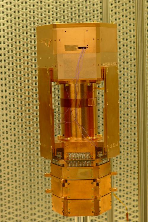 | 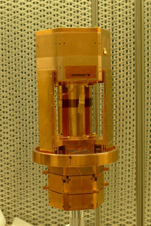 |
| Instead of kapton tape, used a kapton strip (no adhesive) to hold wires down. Strip is taped to itself with copper tape and also some copper tape used to hold it in place on spool. | |