2017/02/14 (Tuesday)
| Setup: DIB1/3/4 → 3.2 MHz filters 3/1/2 → cable 3/1/2 →gender changer 3/1/2 → DCRC55(1)/33(2)/50(3) (on/on/off) | |
| 0855 | Tower/MC/Coldplate = 34.5/31.0/196 mK, Still = 1.26 K / 0.110 mbar, G1/G2 = 200/190 mbar, 1K Pot = 1.683 K / 28 mbar, Main bath = 71.4%. Boil off rate: |
| 0900 | Fill LN2 cold trap bath |
| 1115 | Try DIB1pD IbIs again. This time set front-end gain to 30 (above this the high-frequency oscillations get pretty big). Start at 300 μA and work down to zero. Produce a rough curve, looks nice and continuous. Start again to get more detail and precision. |
| 1230 | Complete DIB1pD IbIs. |
| 1325 | Begin looking at DIB3 IbIs curves on DCRC2. This is the RevC.0 board. Previously this board's front-end gains had to be set smaller (to 2) than for the RevC.1 boards (to 5) in order to avoid excessive high-frequency noise. Looking at DIB3pB (DCRC2pB). High-f noise becomes very strong at FEG=7. Try IbIs at FEG=2 and FEG=6 in s/c range, look for differences. |
| 1545 | Curious about differences in FEG behavior between RevC.0 and RevC.1. Checking output on Telnet as we enter different FEGs through the MIDAS DCRC control (rd 39 for pB). It looks like the setting is the same for both, i.e. the same entry in the DCRC control leads to the same hex value in the telnet session. Strangely it is not a linear increase of the address value, rather it increases as the log of the number entered. |
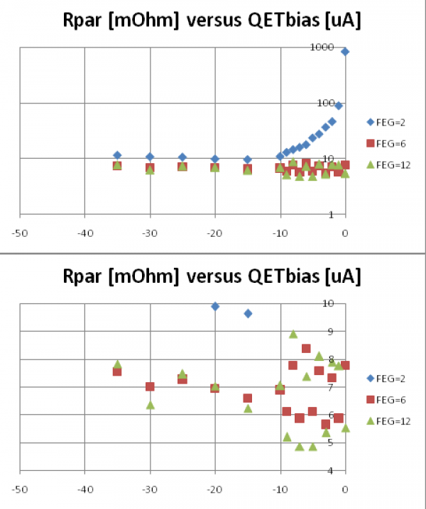 |
| Rparasitic calculated for DIB3pB with three different front-end gains. Upper plot in log scale shows FEG=2 gives real nonsense near Ib=0 and significantly different at higher Ib. Lower plot is a zoom and shows FEG=12 not much different from FEG=6. |
On DIB3pB with FEG=12, high-f noise is huge. But at FEG=6 it's not so bad and it seems to be high enough.
| 1625 | Attempted to make a continuous IbIs curve with DIB3pB. The first issue is that the fixed RevC.0 output gain of x5 (c/w x2 for RevC.1) makes it so the curve won't fit in one full -1.25 to 1.25 V range. But this can be dealt with by shifting the driver offset periodically. Attempted this from -350 uA to peak at -135 uA then down through transition, falling into s/c at -120 uA. Falling into s/c caused a rail, not surprisingly. But then snapping back to transition did not bring the output back to the same place. Tried this twice - each time after falling into s/c then snapping back, it seems that the phase shifted, and a new driver offset was needed. |
|---|---|
| 1739 | Fill LN2 cold trap bath. |