2016/12/20 (Tuesday)
| Status: IVC open, 4K stage removed. Main bath vacuum jacket is evacuated. 1K Pot needle valve closed. Mixture has been pumped out of LN2 trap, traps are at room temperature, still need to be pumped out. Mixture is in dump, fridge evacuated. | |
| G1 has drifted up to 55 mbar overnight, again not sure if this is from the outside air or maybe from the cold traps. Can rule out the latter by pumping the traps out today and seeing whether it goes up as much by tomorrow. | |
| 0845 | Finish drilling second hole through the fridge port for the LHe trap. Takes a long time of constant drilling, maybe 20 minutes. Used #44 drill bit. |
| 0900 | Open Trap 1 to G1. G1 increases from 55.6 to 103.1, so 47.5 mbar in trap according to G1. Open to P2, after first pumping out P2 volume. P2 shows 45 mbar in trap. Pump out Trap 1 with 4He pump. |
| 0910 | Open Trap 2 to G1. I opened v12b first, and the G1 pressure immediately started to increase, indicating leak through the speedivalve, even though it was close pretty tightly. After opening the speedivalve G1 increases to 717.8 mbar, quite high. Open to P2, G1 falls to 295.8 mbar, P2 = 120 mbar (probably not very accurate for the Pirani gauge). Pump out Trap 2 with 4He pump. |
| 1025 | S101 shipping vessel pressure = 10.8 PSI, higher now that it's warm |
|---|
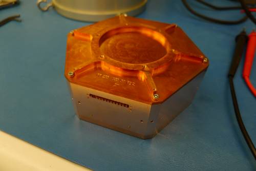
| Detector | S101 | DIB | 1 | |
|---|---|---|---|---|
| date/who: | 2016-12-20 | NM MF | ||
| +lead | - lead | signal | typical | measured |
| 1 | 2 | QET A | 100 to 200 Ω | 303 Ω |
| 3 | 4 | QET B | 100 to 200 Ω | 359 Ω |
| 5 | 6 | QET C | 100 to 200 Ω | 293 Ω |
| 7 | 8 | QET D | 100 to 200 Ω | 395 Ω |
| 9 | chassis | LED1 Rforward | 8 to 9 MΩ | 560 kΩ |
| 9 | chassis | LED1 Vforward | 1.0 to 1.1 V | 1.042 V |
| chassis | 9 | LED1 Rreverse | <1 nS | 200 kΩ |
| 10 | chassis | LED2 Rforward | 8 to 9 MΩ | 767 kΩ |
| 10 | chassis | LED2 Vforward | 1.0 to 1.1 V | 1.045 V |
| chassis | 10 | LED2 Rreverse | <1 nS | <0.3 nS |
| 11 | 12 | Qo-Qi | n/a | |
| 12 | 11 | Qi-Qo | n/a | |
| 1-8 | chassis | <1 nS | <0.1 nS |
| Detector | S101 | DIB | 3 | |
|---|---|---|---|---|
| date/who: | 2016-12-20 | NM MF | ||
| +lead | - lead | signal | typical | measured |
| 1 | 2 | QET A | 100 to 200 Ω | 13 MΩ |
| 3 | 4 | QET B | 100 to 200 Ω | open |
| 5 | 6 | QET C | 100 to 200 Ω | open |
| 7 | 8 | QET D | 100 to 200 Ω | open |
| 9 | chassis | LED1 Rforward | 8 to 9 MΩ | open |
| 9 | chassis | LED1 Vforward | 1.0 to 1.1 V | open |
| chassis | 9 | LED1 Rreverse | <1 nS | open |
| 10 | chassis | LED2 Rforward | 8 to 9 MΩ | open |
| 10 | chassis | LED2 Vforward | 1.0 to 1.1 V | open |
| chassis | 10 | LED2 Rreverse | <1 nS | open |
| 11 | 12 | Qo-Qi | n/a | |
| 12 | 11 | Qi-Qo | n/a | |
| 1-8 | chassis | <1 nS | <0.11 nS | |
| Additional check of continuity between QETA and QETC | ||||
| 1 | 5 | QET A-C | 3.97 kΩ | |
| 1 | 6 | QET A-C | open | |
| 2 | 5 | QET A-C | 702 kΩ | |
| 2 | 6 | QET A-C | open | |
| Detector | S101 | DIB | 4 | |
|---|---|---|---|---|
| date/who: | 2016-12-20 | NM MF | ||
| +lead | - lead | signal | typical | measured |
| 1 | 2 | QET A | 100 to 200 Ω | 349 Ω |
| 3 | 4 | QET B | 100 to 200 Ω | 420 Ω |
| 5 | 6 | QET C | 100 to 200 Ω | 347 Ω |
| 7 | 8 | QET D | 100 to 200 Ω | 378 Ω |
| 9 | chassis | LED1 Rforward | 8 to 9 MΩ | open |
| 9 | chassis | LED1 Vforward | 1.0 to 1.1 V | open |
| chassis | 9 | LED1 Rreverse | <1 nS | open |
| 10 | chassis | LED2 Rforward | 8 to 9 MΩ | open |
| 10 | chassis | LED2 Vforward | 1.0 to 1.1 V | open |
| chassis | 10 | LED2 Rreverse | <1 nS | open |
| 11 | 12 | Qo-Qi | n/a | |
| 12 | 11 | Qi-Qo | n/a | |
| 1-8 | chassis | <1 nS | <0.1 nS |
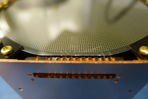
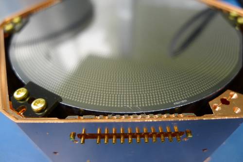
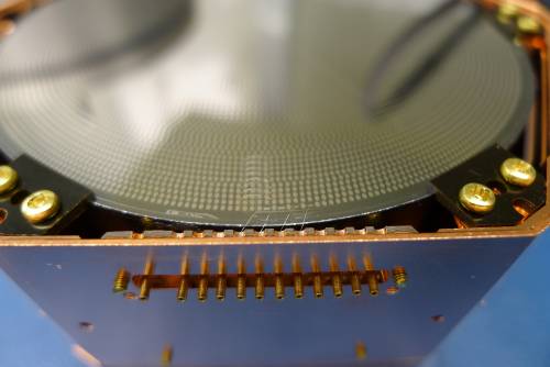
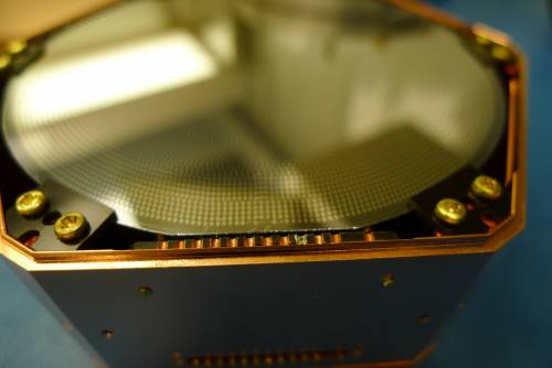
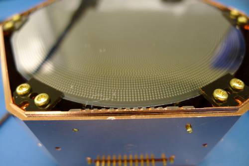
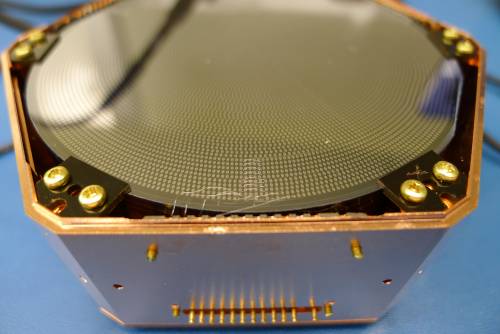
| Side 1 DIB 1 | Side 1 DIB 3 | Side 1 DIB 4 |
|---|---|---|
 |  |  |
| Side 2 DIB 1 | Side 2 DIB 3 | Side 2 DIB 4 |
|---|---|---|
 |  |  |
| 1110 | Put S101 in purge cabinet |
|---|
| 1340 | Begin removing 100 mK stage |
|---|
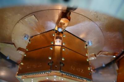 | 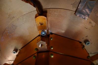 | 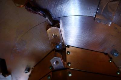 |
In this run the cold plate temperature seemed higher than it should be. I suspected a touch between the 100mK stage and a warmer stage. The 4K stripline “buckle” seemed to be free of the 100mK can. The copper tape around the 600mK rod hole in the 100mK shield did not seem to be touching. The other possible culprit is between the 100mK shields or heat sinks and the 600mK face of the tower. Note that the 100mK section of the tower is almost completely internal, with only the ears sticking out - above the ears is the MC stage and below is the 600mK stage. So if the 100mK heat sinks or shields touch the tower face that's a contact between the 100mK and 600mK stages. The pictures above show no obvious touch but clearly things get pretty close.
| 1420 | Finish removing tower, place tower in clean room |
|---|---|
| 1515 | Put tower in N2 purge cabinet |