2016/10/17 (Monday)
| Setup: DIB1/3/4 → 3.2 MHz filters → cables → DCRC55(1)/nothing/50(3) | |
| Baking overnight, Tower at about 0.55 K until 2:48, then fell to about 36 mK after about 60 minutes | |
| 0900 | Tower/MC/Coldplate = 35.5/36.0/218 mK, Still = 1.23 K / 85 μbar, G1/G2 = 160/165 mbar, 1K Pot = 1.72 K / 40.0 mbar. MB = 67.1% Boiloff rate: again it seems to be somewhere between fast- and slow-mode, a little closer to slow mode |
| 0905 | Fill LN2 cold trap bath |
Look up SQUID settings from August, Run 59. We're using the same SQUETs this run but on different DIBs. Below are the SQUID settings used in Run 59 and the corresponding DIB and DCRC IDs for this run (run 61):
| Run 59 DIB1 = ST-3-9 | Run 59 DIB2 = ST-3-10 | Run 59 DIB3 = ST-3-3 | ||||||
|---|---|---|---|---|---|---|---|---|
| chan | SQUID bias | Lockpoint | chan | SQUID bias | Lockpoint | chan | SQUID bias | Lockpoint |
| pA | -50 | -1.67 | pA | 84.8 | 4.68 | pA | -74 | -3.78 |
| pB | -64.9 | -2 | pB | 86.7 | 3.06 | pB | -81.2 | -3.72 |
| pC | -60.3 | -3.07 | pC | 79.2 | 2.57 | pC | -70 | -1.7 |
| pD | -60.6 | -1.5 | pD | 93.5 | 2.76 | pD | -82.6 | -4.5 |
| Run 61 DIB3 = DCRC2 | Run 61 DIB4 = DCRC3 | Run 61 DIB1 = DCRC1 | ||||||
| 0940 | Apply above settings to the corresponding Run 61 DCRCs, except as per usual use positive values for DCRC2, negative values for DCRCs 1&3 |
|---|---|
| 0940 | Plug DIB3 into DCRC2, power up DCRC2, initiate DCRC2 via telnet session |
| Setup: DIB1/3/4 → 3.2 MHz filters → cables → DCRC55(1)/33(2)/50(3) | |
| 0945 | Disable 15V Power on all three DCRCs to turn off power to FETs. This is at ODB/Equipment/Tower01/Settings/DCRC[1,2,3]/LED/Enable15VPower. |
| 0950 | Stop the TriggerFE, TowerFE, and DCRC Driver programs then start them again. Not sure but maybe this is necessary for the DCRC2 settings to be applied. |
| 0955 | Set up timing link via telnet sessions |
| 0955 | Zap SQUIDs on all three DCRCs (on/off time = 2/30 seconds, iterations = 2) |
| 1015 | DCRC2 was not enabled on the ODB. Enable DCRC2, then zap again |
| 1055 | Observe traces in all phonon channels. Currently all QET biases set to zero. The trace looks different in the non-connected channels, not as choppy. |
| 1105 | Measured the QET bias bias resistor that is used when the test signal is applied. On the RevC.1 boards, DCRC1&3, it's 10 kΩ. On the RevC board, DCRC2, it's 1 kΩ. |
| 1130 | First attempt at measuring Rparasitic and Rnormal of a TES using a triangle-wave test signal. Looking at DIB1pA. Apply 6mVpp 400 Hz test signal. This is dIbias = 0.6 μApp. Output signal is 12 mVpp. Output gain is set to 1; fixed RevC.1 gain = 2, loop gain = 10.5, feedback resistance = 1233 Ω, so dItes = 0.46 μApp. Rpar = Rshunt(dIbias/dItes-1), and Rshunt = 20 mΩ, so Rpar = 5.9 mΩ. Then apply QET bias of -400 μA to drive the TES normal (didn't see a change in output at lower biases - and actually had to wait a minute to see a change even at -400). This time dVout was about 3 mVpp, so Rnormal+Rpar = 83.6 mΩ. |
| 1320 | First attempt at putting the QET into the transition region for electrothermal feedback. Watching the test signal on DIB1pA, set QET bias to -400 μA, then reduce bias until we see the phase of the output triangle wave reverse, then continue to lower the QET bias until the phase goes back to normal. The range seems to be about -190 to -220 μA. Try measuring Rtes at QETbias = -200 μA. dVout = 13 mVpp, and Rtes = Rshunt(1-dIbias/dItes)+Rpar, so we get -3.9+5.9 mΩ = 2 mΩ - oddly low. Correction: Because the output is out of phase, dIbias/dItes is negative - I neglected that in the calculation above. The resulting Rtes = 49.8 mΩ. This is much more plausible. |
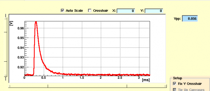 |
| Example pulse on DIB1pA |
|---|
| 1705 | After measuring Tc for DIBs 1/4, we've encountered an issue with sending a test signal down DIB3 (DCRC2). Manually setting the registers in telnet cannot successfully start the test signals either. This will require further investigation. Perhaps the signal generator on DCRC2 is having issues. (A test signal could not be seen on either the Feedback or QET lines when attempted). |
|---|---|
| Instead we've decided to temporarily move DCRC3 over to DIB3 so as to measure the Tc. |
Tc's were measured with a 12 mVpp/400 Hz test signal in the QET bias, with no DC QET bias. Temperature was cycled up then down using the MC heater, with power as high as 60 μW to reach up to Tower = 100 mK. Rate of change of temperature was typically around 5-10 seconds per mK.
| G101c Critical Temperatures | |||||
|---|---|---|---|---|---|
| SC → Transition [mK] | Transition → Normal [mK] | Normal → Transition [mK] | Transition → SC [mK] | ||
| DIB1 pA | missed | missed | 82.5 | 81.8 | TES4 |
| DIB1 pB | 78.6 | 79.4 | 81.3 | 80.2 | TES3 |
| DIB1 pC | 77.5 | 78.0 | 79.4 | 79.1 | TES2 |
| DIB1 pD | 80.3(?) | 80.7 | 83.1 | 82.8 | TES9 |
| DIB3 pA | no TES connected | ||||
| DIB3 pB | 82.1 | 83.5 | 84.7 | 83.8 | TES11 |
| DIB3 pC | 95.0 | 96.4 | 99.1 | 97.4 | TES5 |
| DIB3 pD | no TES connected | ||||
| DIB4 pA | no TES connected | ||||
| DIB4 pB | 80.5 | 81.0 | 81.9 | 81.2 | TES8 |
| DIB4 pC | 79.6 | 80.3 | 80.5 | missed | TES1 |
| DIB4 pD | missed | 78.8 | 80.8 | 80.8 | TES0 |
| 1745 | Fill LN2 cold trap full. |
|---|---|
| 1755 | Main Bath level = 53.5%. |
| 1800 | Reconnect DCRCs in their original setups and zap SQUIDs. |