Previous Day
| Status | Two SQUETs have had their flyover insulation reinforced. Tower not yet assembled. Don't forget to pump out MB vacuum jacket more. |
Options concerning lack of fit between G106a housing far edge and source housing near edge:
Remount G106a in a different housing.
Modify G106a housing without removing detector to correct flaws.
Modify source&thermometer housing to accommodate flaws in G106a housing.
Construct short adapter piece between housings with standard far edge and modified near edge.
1 & 4 would each take a very long time. 1 holds the additional danger of damaging the detector; also we'd need to find a spare housing. 4 has the disadvantage of increasing the distance between sources and detector.
2 is the most attractive option, try to fix the flawed piece. But it would require careful consideration of whether this could be accomplished without damage to the detector, through vibration or debris.
3 is safer then 2, the piece can be disassembled and brought to the shop and cleaned afterward. But it would be somewhat annoying to modify a good piece to fit one bad piece.
| Cleanroom measurements with caliper |
| Source housing (good) |
| Far edge OD, face-to-face | 4.104/4.106/4.100 in |
| Far edge OD, vertex-to-vertex | 4.598/4.596/4.603 in |
| Near edge ID, face-to-face | 4.125/4.122/4.117 in |
| Near edge ID, vertex-to-vertex | 4.617/4.619/4.622 in |
| G106a housing (bad) |
| Far edge OD, face-to-face | 4.109/4.109/4.124 in |
| Far edge OD, vertex-to-vertex | 4.598/4.613/4.587 in |
The largest face-to-face OD on the G106a housing is the DIB1-DIB2 distance. As can be seen, the largest face-to-face ID on the source housing near edge is just barely bigger (1 mil) than the largest face-to-face OD on the G106a housing far edge.
At a guess the design specs were 4.100 for far edge face-to-face OD and 4.120 for near edge face-to-face ID leaving 10 mil clearance on each side. Then the largest OD on G106a's far edge exceeds the tolerance by 4 mil total.
| 1015 | Found an orientation in which the source housing fits onto the G106a housing: the thermometer slot (slot nearest the serial number) of the source housing is aligned with DIB1 of the G106a housing. |
| 1110 | Attach detector and source housing to tower with four threaded rods. Attach Z1-1-6, Z1-1-9, and Z1-1-11 to DIBs 1, 2, and 3, respectively. |
| | When attaching Z1-1-11, it was noticed that the screws connecting the SCAB (12-pin connector) to the chassis of the side coax, are longer than on other side coaxes. These longer screws contact the chassis of the detector at an earlier point in connecting the side coax, which means that the pins on the SCAB don't insert into the DIB as far as for the other side coaxes. The pin connections seem good enough, but we'll see what the electrical check says. |
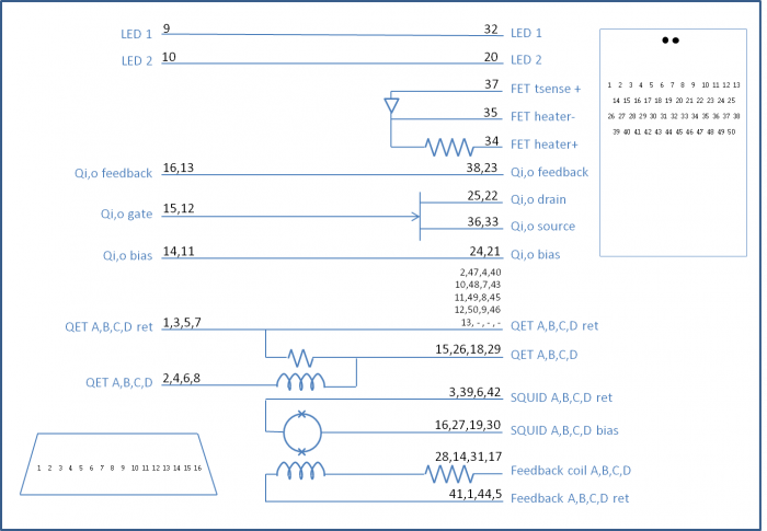
| SQUET wiring diagram |
 |
| Detector | G106a | DIB | 1 | |
| side coax | ZB1-6 | date/who: | 2015-06-22 | NM, AK & AV |
| face | 2 | | | |
| +lead | - lead | signal | typical | measured |
| 1 | 2 | QET A | 100 to 200 Ω | open |
| 2 | 4 | QETA-B | 100 to 200 Ω | open |
| 3 | 4 | QET B | 100 to 200 Ω | open |
| 4 | 6 | QETB-C | 100 to 200 Ω | open |
| 5 | 6 | QET C | 100 to 200 Ω | open |
| 6 | 8 | QETC-D | 100 to 200 Ω | open |
| 7 | 8 | QET D | 100 to 200 Ω | open |
| 2 | 8 | QETA-D | 100 to 200 Ω | open |
| 9 | chassis | LED1 Rforward | 8 to 9 MΩ | 753 kΩ |
| 9 | chassis | LED1 Vforward | 1.0 to 1.1 V | 1.089 V |
| chassis | 9 | LED1 Rreverse | <1 nS | <0.2 nS |
| 10 | chassis | LED2 Rforward | 8 to 9 MΩ | open |
| 10 | chassis | LED2 Vforward | 1.0 to 1.1 V | 1.098 V |
| chassis | 10 | LED2 Rreverse | <1 nS | <.2 nS |
| 1 | 11 | Qo Rbias | 24 to 26 nS | <.1 nS |
| 12 | 11 | Qo C coupling | <1 nS | <0.2 nS |
| 12 | 13 | Qo Rfeedback | 24 to 26 nS | 26 nS |
| 1 | 14 | Qi Rbias | 24 to 26 nS | <.4 nS |
| 15 | 14 | Qi C coupling | <1 nS | <0.2 nS |
| 15 | 16 | Qi Rfeedback | 24 to 26 nS | 26 nS |
| Detector | G106a | DIB | 2 | |
| side coax | ZB1-1-9 | date/who: | 2015-06-22 | NM, AK & AV |
| face | 5 | | | |
| +lead | - lead | signal | typical | measured |
| 1 | 2 | QET A | 100 to 200 Ω | 195 Ω |
| 2 | 4 | QETA-B | 100 to 200 Ω | 179 Ω |
| 3 | 4 | QET B | 100 to 200 Ω | 120 Ω |
| 4 | 6 | QETB-C | 100 to 200 Ω | 178 Ω |
| 5 | 6 | QET C | 100 to 200 Ω | 165 Ω |
| 6 | 8 | QETC-D | 100 to 200 Ω | 169 Ω |
| 7 | 8 | QET D | 100 to 200 Ω | 120 Ω |
| 2 | 8 | QETA-D | 100 to 200 Ω | 164 Ω |
| 9 | chassis | LED1 Rforward | 8 to 9 MΩ | 740 kΩ |
| 9 | chassis | LED1 Vforward | 1.0 to 1.1 V | 1.085 V |
| chassis | 9 | LED1 Rreverse | <1 nS | <0.2 nS |
| 10 | chassis | LED2 Rforward | 8 to 9 MΩ | 717 kΩ |
| 10 | chassis | LED2 Vforward | 1.0 to 1.1 V | 1.085 V |
| chassis | 10 | LED2 Rreverse | <1 nS | <1.5 nS |
| 1 | 11 | Qo Rbias | 24 to 26 nS | 25 nS |
| 12 | 11 | Qo C coupling | <1 nS | <0.2 nS |
| 12 | 13 | Qo Rfeedback | 24 to 26 nS | 26 nS |
| 1 | 14 | Qi Rbias | 24 to 26 nS | 26 nS |
| 15 | 14 | Qi C coupling | <1 nS | <0.2 nS |
| 15 | 16 | Qi Rfeedback | 24 to 26 nS | 26 nS |
| Detector | G106a | DIB | 3 | |
| side coax | ZB1-1-11 | date/who: | 2015-06-01 | NM, AK & AV |
| face | 6 | | | |
| +lead | - lead | signal | typical | measured |
| 1 | 2 | QET A | 100 to 200 Ω | 186 Ω |
| 2 | 4 | QETA-B | 100 to 200 Ω | 221 Ω |
| 3 | 4 | QET B | 100 to 200 Ω | 202 Ω |
| 4 | 6 | QETB-C | 100 to 200 Ω | 166 Ω |
| 5 | 6 | QET C | 100 to 200 Ω | 152 Ω |
| 6 | 8 | QETC-D | 100 to 200 Ω | 165 Ω |
| 7 | 8 | QET D | 100 to 200 Ω | 147 Ω |
| 2 | 8 | QETA-D | 100 to 200 Ω | 192 Ω |
| 9 | chassis | LED1 Rforward | 8 to 9 MΩ | 755 kΩ |
| 9 | chassis | LED1 Vforward | 1.0 to 1.1 V | 1.083 V |
| chassis | 9 | LED1 Rreverse | <1 nS | <11 MΩ |
| 10 | chassis | LED2 Rforward | 8 to 9 MΩ | 142 kΩ |
| 10 | chassis | LED2 Vforward | 1.0 to 1.1 V | 1.065 V |
| chassis | 10 | LED2 Rreverse | <1 nS | closed |
Check face 2 tower wires. All read about 30 Ω, and nothing was open.
| Detector | G106A | DIB | 1 | |
| | | date/who: | 2015-03-23 | DS NM |
| +lead | - lead | signal | typical | measured |
| 1 | 2 | QET A | 100 to 200 Ω | 30.0 Ω |
| 3 | 4 | QET B | 100 to 200 Ω | 91.5 Ω |
| 5 | 6 | QET C | 100 to 200 Ω | 89.6 Ω |
| 7 | 8 | QET D | 100 to 200 Ω | 58.0 Ω |
| 9 | chassis | LED1 Rforward | 8 to 9 MΩ | 760 kΩ |
| 9 | chassis | LED1 Vforward | 1.0 to 1.1 V | 1.040 V |
| chassis | 9 | LED1 Rreverse | <1 nS | <1 nS |
| 10 | chassis | LED2 Rforward | 8 to 9 MΩ | 739kΩ |
| 10 | chassis | LED2 Vforward | 1.0 to 1.1 V | 1.040 V |
| chassis | 10 | LED2 Rreverse | <1 nS | <1 nS |
| 11 | 12 | Qo-Qi | | 55.6Ω |
| 12 | 11 | Qi-Qo | | 53.4Ω |
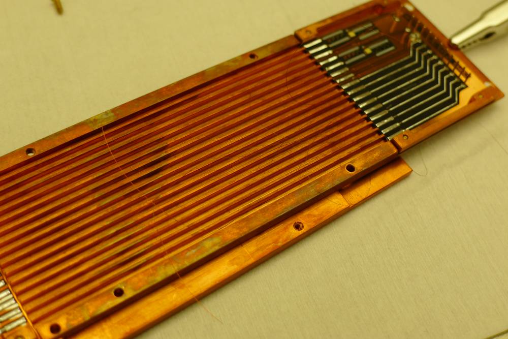
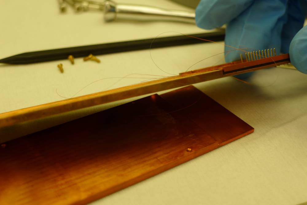
| 1630 | The problem causing the open phonon channels on DIB1 is the side coax ZB1-6. Wires 1-8 are all open. Taking off the cover plate shows that these 8 wires - the phonon wires - are all completely sprung, broken from the solder at the tower end. |
| | Below are measurements related to the charge channels. All appear to be fine. |
| Side coax | ZB1-6 |
| | date: | 2015-06-22 | who: | MF NM AK AV |
| +lead | - lead | signal | typical | measured |
| | | | |
| D11 | T11 | Qo Rbias | 25 nS | 26 nS |
| T12 | T13 | Qo Rfeedback | 25 nS | 26 nS |
| D11 | T12 | Qo C coupling | <1 nS | 0.1 nS |
| D12 | T14 | Qi Rbias | 25 nS | 26 nS |
| T15 | T16 | Qi Rfeedback | 25 nS | 26 nS |
| D12 | T15 | Qi C coupling | <1 nS | 0.2 ns |
| Broken wires on ZB1-1-6 |
 |
 |
Next Day