Previous Day
Tower electrical checkout
| USD1 pinout map |
| DIB1qO | DIB1qI | DIB2qO | DIB2qI | DIB1pin7 |
| q1 | q3 | q2 | q4 | g |
| Charge channels are numbered outer-to-inner |
| A “1” is scratched onto housing above DIB1 (a little hard to see) |
| DIB1 is the DIB nearest to the housing serial number |
| Detector | USD1 | DIB | 1 | |
| side coax | ZB1-1-11 | date/who: | 2016-05-25/NM&DS | |
| face | 1 | | | |
| + lead | -lead | signal | typical | measured |
| 9 | chassis | LED1 Rforward | 8 to 9 MΩ | 777kΩ |
| 9 | chassis | LED1 Vforward | 1.0 to 1.1 V | 1.1V |
| chassis | 9 | LED1 Rreverse | <1 nS | 0.2nS |
| 10 | chassis | LED2 Rforward | 8 to 9 MΩ | 772kΩ |
| 10 | chassis | LED2 Vforward | 1.0 to 1.1 V | 1.1V |
| chassis | 10 | LED2 Rreverse | <1 nS | 0.7nS |
| 11 | 7 | Qo Rbias | 24 to 26 nS | Open |
| 11 | 12 | Qo C coupling | <1 nS | .2nS |
| 13 | 12 | Qo Rfeedback | 24 to 26 nS | 25.5nS |
| 14 | 7 | Qi Rbias | 24 to 26 nS | Open |
| 14 | 15 | Qi C coupling | <1 nS | 0.05nS |
| 16 | 15 | Qi Rfeedback | 24 to 26 nS | 25.5nS |
| 1-8, 11-16 | chassis | Chassis shorts | <1 nS | <1nS Except Pin7 |
| | In this tower level check out, Pin 7 → Chassis was ~50-500Ω. Tapping on the detector housing could change it. Removing the side coax and measuring directly on the DIB yields the same result. |
| Detector | USD1 | DIB | 1 | |
| | | date/who: | 2016-05-23 | AK NM |
| +lead | - lead | signal | typical | measured |
| 9 | chassis | LED1 Rforward | 8 to 9 MΩ | 780 kΩ |
| 9 | chassis | LED1 Vforward | 1.0 to 1.1 V | 1.061 V |
| chassis | 9 | LED1 Rreverse | <1 nS | <.5 nS |
| 10 | chassis | LED2 Rforward | 8 to 9 MΩ | 783kΩ |
| 10 | chassis | LED2 Vforward | 1.0 to 1.1 V | 1.061 V |
| chassis | 10 | LED2 Rreverse | <1 nS | <.5 nS |
All pins to chassis measured at <1 nS, except pin 7, which read 43.7 Ω.
| Detector | USD1 | DIB | 2 | |
| | | date/who: | 2015-05-25 | AK NM |
| +lead | - lead | signal | typical | measured |
| 9 | chassis | LED1 Rforward | 8 to 9 MΩ | 763kΩ |
| 9 | chassis | LED1 Vforward | 1.0 to 1.1 V | 1.061V |
| chassis | 9 | LED1 Rreverse | <1 nS | < 1 nS |
| 10 | chassis | LED2 Rforward | 8 to 9 MΩ | 783 kΩ |
| 10 | chassis | LED2 Vforward | 1.0 to 1.1 V | 1.061V |
| chassis | 10 | LED2 Rreverse | <1 nS | <1 nS |
All pins to chassis measure <1 nS, except pin 11 which read 34 Ω.
| USD1 pinout map |
| DIB1qO | DIB1qI | DIB2qO | DIB2qI | DIB1pin7 |
| q1 | q3 | q2 | q4 | g |
| Charge channels are numbered outer-to-inner |
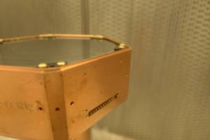
| A “1” is scratched onto housing above DIB1 (a little hard to see) |
| DIB1 is the DIB nearest to the housing serial number |
| | q1 | q2 | q3 | q4 | g | chassis |
| q1 | - | open | open | open | open | open |
| q2 | - | - | open | open | open | 49.6 |
| q3 | - | - | - | open | open | open |
| q4 | - | - | - | - | 10.9 | open |
| g | - | - | - | - | - | 32.6 |
resistances between four charge channels
and ground connection on opposite side |
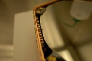
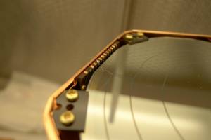
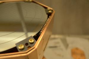
It appears that all of the wirebonds from DIB to detector are broken (and two are in contact with the housing). That sucks.
| Repairing USD1 wirebonds |
| 1500 | Take USD1 to wirebonding lab. For DIB-to-detector bonds use these bonder settings: bond1/2 power = 480/475, bond1/2 time = 40/30, loop height / drop before clamp = 50/20 mils. |
| 1505 | Examine charge side. Both the DIB-to-detector bonds on DIB1 were loose at the DIB. Removed these. DIB2qI wirebond was completely missing. DIB2qO wirebond appeared to be intact. |
| 1525 | Redo DIB2qI DIB-to-detector bond. |
| 1530 | Redo DIB1qO DIB-to-detector bond. |
| 1535 | Redo DIB1qI DIB-to-detector bond. |
| 1545 | Examine ground side. Both DIB1p7 DIB-to-detector bonds appear intact. |
| 1550 | All connections check out with multimeter: continuity between all charge channels and the ground pin, LEDs all look OK too. Return USD1 to clean room. |
| 1620 | Enter cleanroom with newly wirebonded USD1 to perform first a detector electrical check, then a tower check. |
| USD1 pinout map |
| DIB1qO | DIB1qI | DIB2qO | DIB2qI | DIB1pin7 |
| q1 | q3 | q2 | q4 | g |
| Charge channels are numbered outer-to-inner |
| A “1” is scratched onto housing above DIB1 (a little hard to see) |
| DIB1 is the DIB nearest to the housing serial number |
| | q1 | q2 | q3 | q4 | g | chassis |
| q1 | - | 21.5 | 36.5 | 49.8 | 14.8 | open |
| q2 | - | - | 33.9 | 39.1 | 11.2 | open |
| q3 | - | - | - | 60.5 | 27.0 | open |
| q4 | - | - | - | - | 34.8 | open |
| g | - | - | - | - | - | open |
resistances between four charge channels
and ground connection on opposite side |
| All 4 LEDs show expected resistances |
| 1625 | Build tower with DIB1 placed above Face 1 (ZB-10). |
| | |
| Detector | USD1 | DIB | 1 | |
| side coax | ZB1-1-11 | date/who: | 2016-05-25/AK&DS | |
| face | 1 | | | |
| + lead | -lead | signal | typical | measured |
| 9 | chassis | LED1 Rforward | 8 to 9 MΩ | 780kΩ |
| 9 | chassis | LED1 Vforward | 1.0 to 1.1 V | 1.105V |
| chassis | 9 | LED1 Rreverse | <1 nS | <0.2nS |
| 10 | chassis | LED2 Rforward | 8 to 9 MΩ | 781kΩ |
| 10 | chassis | LED2 Vforward | 1.0 to 1.1 V | 1.107V |
| chassis | 10 | LED2 Rreverse | <1 nS | <0.8nS |
| 11 | 7 | Qo Rbias | 24 to 26 nS | 26nS |
| 11 | 12 | Qo C coupling | <1 nS | <.2nS |
| 13 | 12 | Qo Rfeedback | 24 to 26 nS | 26nS |
| 14 | 7 | Qi Rbias | 24 to 26 nS | 25nS |
| 14 | 15 | Qi C coupling | <1 nS | <0.2nS |
| 16 | 15 | Qi Rfeedback | 24 to 26 nS | 26nS |
| 1-8, 11-16 | chassis | Chassis shorts | <1 nS | <1nS |
| Detector | USD1 | DIB | 2 | |
| side coax | ZB1-6 | date/who: | 2016-05-25/AK&DS | |
| face | 4 | | | |
| + lead | -lead | signal | typical | measured |
| 9 | chassis | LED1 Rforward | 8 to 9 MΩ | 759kΩ |
| 9 | chassis | LED1 Vforward | 1.0 to 1.1 V | 1.107V |
| chassis | 9 | LED1 Rreverse | <1 nS | <2.0nS |
| 10 | chassis | LED2 Rforward | 8 to 9 MΩ | 780kΩ |
| 10 | chassis | LED2 Vforward | 1.0 to 1.1 V | 1.107V |
| chassis | 10 | LED2 Rreverse | <1 nS | <0.3nS |
| 11 | 7 | Qo Rbias | 24 to 26 nS | 27nS |
| 11 | 12 | Qo C coupling | <1 nS | <.5nS |
| 13 | 12 | Qo Rfeedback | 24 to 26 nS | 26nS |
| 14 | 7 | Qi Rbias | 24 to 26 nS | 25nS |
| 14 | 15 | Qi C coupling | <1 nS | <0.2nS |
| 16 | 15 | Qi Rfeedback | 24 to 26 nS | 26nS |
| 1-8, 11-16 | chassis | Chassis shorts | <1 nS | <1nS |
| 1710 | Looking good. Attach adapter plate. |
Next Day