2016/04/18 (Monday)
| Status: LN in bath, IVC still has 1.6 mbar He exchange gas | |
| 0845 | MC/Sorb = 77/130 K, IVC = 1.6 mbar |
| 0845 | Begin pumping out IVC with scroll pump |
| 0850 | Begin pumping out IVC with turbo pump |
| 0900 | IVC = 12 E-6mbar (pumping pressure) |
| 0910 | IVC = 7.4 E-6mbar (pumping pressure) |
| 0915 | Perform 77K electrical checkout. |
77K Electrical Checkout Anomalies:
- DIB1, Qi/Qo bias to QET return reads nearly open, less than 1 nS. Suggests poor connectivity to/through crystal
- Same for DIB2 except for QET Returns A and B. So probably this is all in the phonon connections, and apparently the connections to DIB2 A&B are ok. (Not really - see below)
- note that both of the above were also seen in the previous run with this crystal (2013 Nov 20, Run 47)
- DIB2 Feedback A reads high and unstable resistance, 500-900 kΩ (should be 9-13 kΩ)
Investigating inter-channel resistances: checked cross-channel QET returns, and cross-channel QET biases on all three DIBs. Found the following pattern:
- same-side cross-channel resistances ~ 1 MΩ
- opposite-side cross-channel resistances OPEN (on Ω-scale)
However, on DIB3, the OPEN cases are all DIB3pD to another channel, suggesting that DIB3pD is on the opposite side from DIB3pA,B,C. But the iZIPv6 map says DIB3pC is the opposite-side channel (Side1pE), and DIB3pA,B,D are together on Side 2. Is the map incorrect for this crystal? (Was it correct for G106a?)
The high opposite-side resistances explain why the DIB2 Q bias connections to DIB2pA,B read open. But this would suggest that DIB1's Q bias lines should show connectivity to DIB1pA,B,C. But they don't. So maybe the Side 1 charge channels are not well connected to the crystal.
The detector electrical checkout shows very high Qi-Qo resistances on Side 2. It would make more sense with the above observations if the high resistances were seen on the DIB1 Q's.
| 1015 | Turn on leak detector |
|---|---|
| 1020 | IVC = 3.4 E-6mbar (pumping pressure) |
We've discovered a different iZIPv6 layout diagram than the one we've been using. The one we've been using is labeled G103a, 6/21/2012 and is found here: G103a map. The other one is labeled iZIPv6 6/15/2012 and is found here: G106a map, which is a Confluence page specifically for G106a.
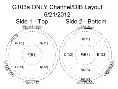 | 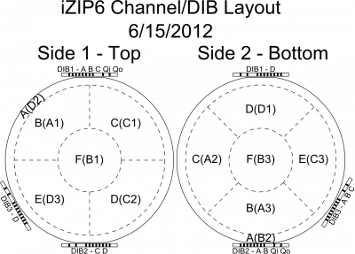 |
Apparently we've been using the wrong map for G106a. DIB3pC/D should correspond to Side2/1pE. The incorrect map has DIB3pC/D corresponding to Side1/2pE.
| 1040 | IVC = 3.0 E-6mbar (pumping pressure), 34 E-6mbar (pump valved out) |
|---|---|
| 1055 | Valve out turbo and begin leak checking IVC. Background is about 220 pbarL/s. |
| 1105 | Begin blowing out LN. |
| 1110 | LD = 180 pbarL/s |
| 1125 | LD = 146 pbarL/s |
| 1150 | LD = 115 pbarL/s |
| 1210 | LD = 98 pbarL/s |
| 1210 | Cease LN2 blowout. Repower He4 pump and commence pumping out Main Bath to make sure all the LN2 has been removed. |
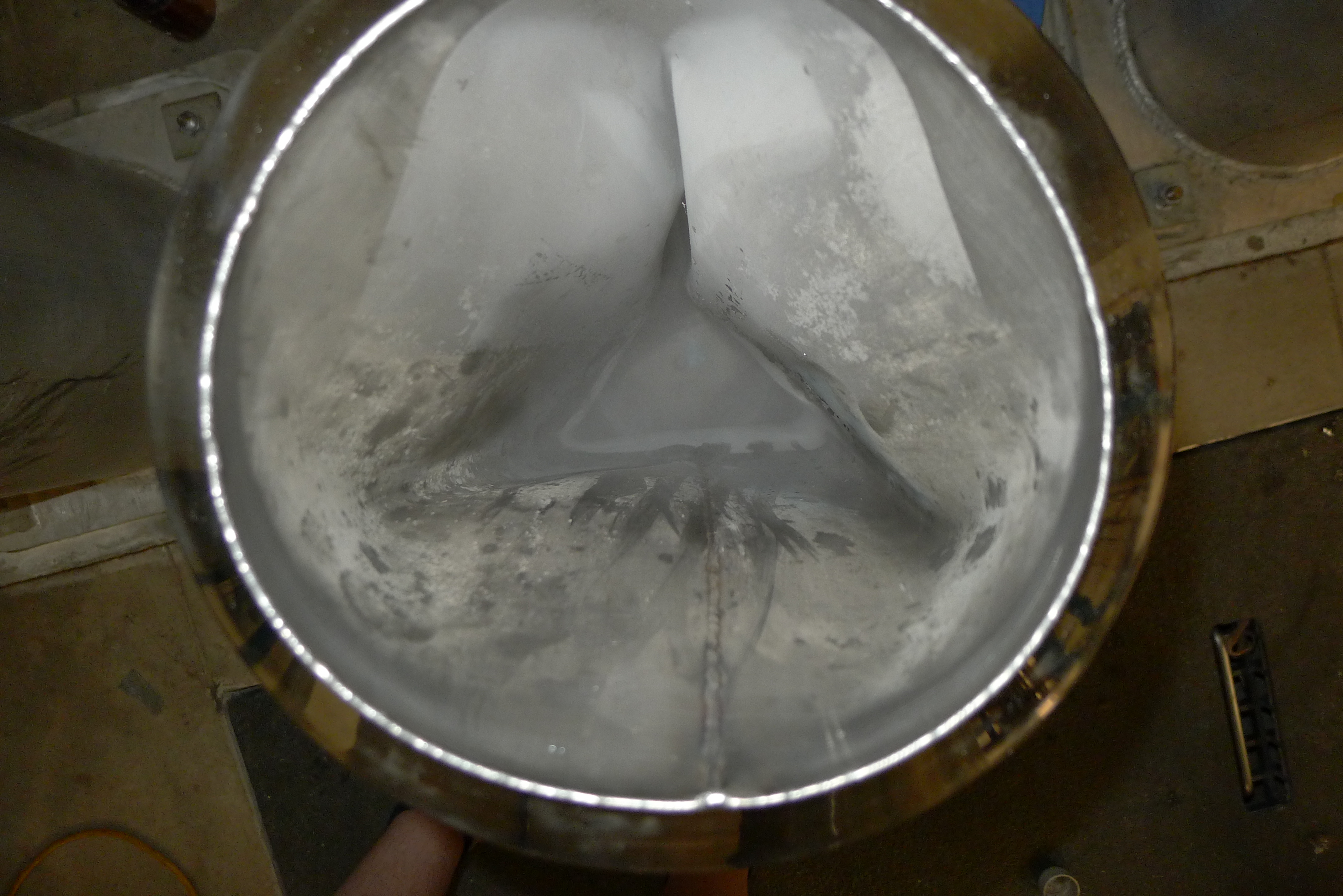
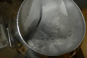
| 1211 | During blowout, use LN2 to fill the cold trap bath. Last week, the bath had warmed up with the cold traps inside. We were then unable to remove the cold traps from the bath – they felt stuck. Today after adding the LN2 and cooling the traps down again, we were able to free them. We removed the traps, and stopped adding LN2 to the cold trap bath, to allow it to again warm up. Upon initial inspections, the inside jacket of the trap bath had ballooned outwards forming a sort of triangular cavity for the traps to sit in. This is most likely what had caused the stuck traps in the first place. |
| During the warmup process, there were two loud metallic sounds that presumably signaled more changes in shape of the inside jacket of the trap bath. There appears to be a vacuum port on the bottom of the bath that might be used for pumping out the jacket and hopefully remedying the situation. Currently researching this trap on Oxford's website. |
| Images of LN2 Cold Trap Bath After Warm Up | |
|---|---|
 |  |
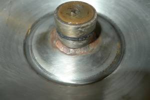 | 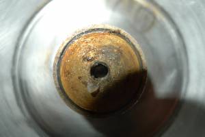 |
| 1225 | P2 below 0.5mbar. Flush Main Bath with He gas. Evacuate 1K Pot. |
|---|---|
| 1300 | Using a replacement cold trap bath borrowed from the Goldman lab, place LN2 cold traps into bath and fill with LN2. In preparation for throughput test. |
| 1320 | We're going to perform a standard throughput test so we won't run the mixture through the cold traps. We'll clean the mixture after this, though. |
| 1325 | Open leak checker to IVC to get a background leak rate of 6.5E-8 mbarL/s. |
| 1346 | Perform throughput test, with a G1 increasing at a rate of 3 mbar/min and quickly stabling at about 37 mbar. Something is wrong, though perhaps the procedure was done incorrectly. Pump to dump to perform test again. During test leak rate remained stable at 6.7E-8 mbarL/s. |
| 1405 | Perform a second throughout test and again find a flow rate of roughly 2 mbar/min. During the test G1 dropped from 706 mbar to a minimum of 32 mbar before stabilizing at 36 mbar. In past throughout tests, G1 reached a minimum of ~100 mbar before rising, so this is indicative of an issue. A likely cause is dirty mixture, since coldtrap cleaning was delayed by the dewar issues stated above. Pump mixture to dump and prepare to remove He cold trap from the bath, as it is a likely candidate for a block. |
| 1425 | G1 = 2 mbar, G2 = 783 mbar, P1 = 17 ubar. All IVC valves closed. Condenser and Still Pumping manual valves open. |
| 1430 | Remove LHe trap from MB to let warm up. |
| 1445 | LHe trap is nearly at room temperature but P1 has not increased. P1 = 18 ubar. |
| actually, it probably would have made more sense to have V1 open and the condenser valve closed to monitor the LHe pressure on G1. As it is, any expanding gas will have to go through the fridge impedance first to show up on P1. | |
| 1450 | Open V1. No significant change on G1, stays around 1.6 mbar. Close V1 again. |
| 1503 | Close Condenser Line Speedivalve so that anything that is still in the LHe trap can't travel into the cold fridge. Though it may have already done so, but just to be safe. Open V13A, V1A, V5 to pump whatever is still in the LHe cold trap into the LN2 cold trap 1. So that any pollutants will be frozen in the LN2 cold trap. |
| 1510 | Close V1A, V13A and open V9, V12A, and Cold Trap 1 speedivalve to pump whatever mixture is in Cold Trap 1 back to the dump. |
| Before opening the cold trap 1 speedivalve, check G2 to see how much mixture is in the dump to start with. G2 reads 752mbar. Open Cold Trap 1 speedivalve and G2 begins rising. Currently at 775mbar and still rising. | |
| 1525 | G2 settles at 785mbar. That extra 30mbar may have been residing in the LN2 Cold Trap while performing the throughput test, or it may have been left over in the fridge. It's hard to say, but now we'll see if we can do another throughput. Place LHe cold trap back in Main Bath to cool it down to ~77K before performing throughput test. |
| 1530 | Throughput test fails, indicating blockage inside fridge lines. Pump mixture back to dump from both sides of fridge. |
| 1540 | MC (Cernox) = 77.9 K. Still = 2.207 kΩ. |
| 1620 | After pumping to dump for ~20 minutes, G1: 2.0mbar, G2; 785.5mbar, P1: 16ubar. Turn on Mixing Chamber Heater to 20mW and turn on Still heater gradually increasing by 2mW approximately every 30s. Monitor all gauges to see if anything melts out of fridge lines and adds to the pressures. |
| 1623 | We were still pumping on IVC with leak checker. Switch back to turbopumping IVC. |
| 1625 | Remove LHe cold trap from Main Bath again to reduce volume of cold fridge lines – hopefully increasing chance that we can boil off whatever blockage there is. |
| 1620 | Begin applying a little Still heat (less than 20 mW) |
| 1630 | MC = 78.3 K. Still = 2.221 kΩ. |
| 1640 | Increase Still heat to 120 mW |
| 1700 | Increase Still heat to 199.99 mW (max output). G2 has risen, though insignificantly, to 786.3mbar. The pressure does oscillate somewhat, though we will see what leaving the heater at max for several minutes does. |
| 1725 | With Still heat still at max, close V6 and then V1, V5, so that mixture is isolated in dump. G2 has risen to consistently be above 786.6mbar, and has settled around 787.0mbar. Clean mixture through Cold Trap 1 for 5 minutes. Turn off Still heater and Mixing Chamber heater in preparation for another through put test. |
| Let mixture from dumb backflow into Cold Trap 1. Then when I opened V14 I realized that the Gate Valve was still open, which would have let mix back into the fridge from the still side. Immediately close every valve. Open V9 and V6 to pump to dump again. Hopefully not much mix got into the fridge. | |
| 1735 | Once V6 had opened all the way, all the gauges were reading the same values: G1: ~2.0mbar, G2:787.0mbar, P1; 16ubar. So things appear to be in the same state. Close V6, and when that's done, close the condenser speedivalve and gate valve for quick-cleaning. |
| 1745 | Place LHe cold trap back in main bath in preparation for throughput check. |
| 1748 | Commence cryocleaning mixture through Cold Trap 1. |
| 1805 | Cease cryocleaning mixture. Pump to dump. |
| 1819 | Throughput test showed no improvement in rate, which G1 stabilizing at 42 mbar. I guess we have a block somewhere within the fridge lines. Pump mixture to dump. Isolate fridge lines. Add 1 mbar He exchange gas to IVC. Close gate and condenser line speedivalves. |
| 1830 | Isolate the dump with G2= 786.4 mbar. Pump He gas out of main bath and flush warm He gas, over-pressurized to 77 mbarf over atmosphere. |
| 1835 | Mixing chamber at 86 K and climbing. Turn off still heater. |