Table of Contents
2013/03/06
Beta Source Holder
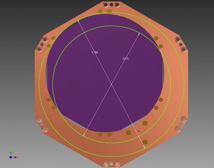
A source holder plate was designed by us and fabricated by our mechanical workshop to hold Queens' Pb-210 beta source and an Am-241 source (engineering drawing). The source holder plate was designed under the assumption that Qi is of diameter 3.071“ and Qo is of diameter 3.780”.
The Pb-210 source was designed to fasten onto the pillars in a 3“ detector housing, so these measurements were used to define the position of the holes and the diameter of the source was overestimated slightly to ensure it fit. Its position is offset from the centre of the plate to allow for the inclusion of an Am-241 source. The following is copied from Wolfgang's email regarding the production of the Pb-210 source:
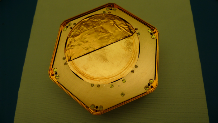
We attached the plate to a cylindrical Al vessel and sealed with a rubber o-ring. In the active side you see a hint of where the o-ring was. The activity would be found only inside this circle.
The Am-241 source is of the same design as that used for Q4 in the 4Q 100 mm device, ie. the collimation hole is offset from the centre. This enables us to position the collimation hole over Qi and further away from the Qi-Qo boundary. We estimate that the collimation hole will result in an event rate of 20 Hz from this source.
The Pb-210 source from Queens arrived on Monday 4th March and Andy from radiation services came round to perform a swab test on Tuesday 5th March. The source was shipped with a 3” holder, and the inside copper surface of this holder that faced the active area of the source was tested. The source arrived with shielding in the form of copper tape across half its surface, therefore reducing its effective activity to around 10 Bq.
After much deliberation, we decided to keep the copper shielding. Therefore, the sources should yield a total event rate of 30 Hz. Additionally, the shielding was placed such that it covered Qo, ensuring the rest of the active surface lay over Qi.
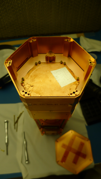
Finally we also decided to place the source over Side 2 as Qi appeared to be quieter during Run 28. This could, however, be due to the DCRC rather than the charge electrodes themselves. The disadvantage with Side 2 is the noisy Qo channel. However, this should not be a problem as we shall be using a smaller trace length of 0.4096 ms and the oscillation in the baseline appears to be of a longer period. Additionally, something may have caused Qo to behave this way during Run 28, and as we do not know the cause, we cannot say with certainty that the oscillations would reoccur.
| Figure 1: Sketch of Assembled Beta Source Holder. Circles represent boundaries of Qi & Qo. |
|---|
 |
| Figure 2: Assembled Beta Source Holder. |
|---|
 |
| Figure 3: Beta Source Holder Mounted facing Side 2. |
|---|
 |
| 0055 | Conduct tower level continuity checks: |
|---|
| Detector | G102 | DIB | 1 | |
|---|---|---|---|---|
| side coax | ZB1-1-6 | date/who: | 2013-03-06 | HC |
| face | 2 | |||
| +ve lead | -ve lead | signal | measured | |
| 7 | 8 | QET D | 300 Ω | |
| 9 | chassis | LED1 Rforward | 760 kΩ | |
| 10 | chassis | LED2 Rforward | - | |
| 9 | chassis | LED1 Vforward | 1.103 V | |
| 10 | chassis | LED2 Vforward | - | |
| chassis | 9 | LED1 Greverse | <0.7 nS | |
| chassis | 10 | LED2 Greverse | - | |
| 7 | 11 | Qo Rbias | 26 nS | |
| 12 | 11 | Qo C coupling | <0.1 nS | |
| 12 | 13 | Qo Rfeedback | 26 nS | |
| 7 | 14 | Qi Rbias | 26 nS | |
| 15 | 14 | Qi C coupling | <0.1 nS | |
| 15 | 16 | Qi Rfeedback | 26 nS | |
| No shorts to ground | ||||
| Detector | G102 | DIB | 2 | |
|---|---|---|---|---|
| side coax | ZB1-1-9 | date/who: | 2013-03-06 | HC |
| face | 5 | |||
| +ve lead | -ve lead | signal | measured | |
| 7 | 8 | QET D | 310 Ω | |
| 9 | chassis | LED1 Rforward | 779 kΩ | |
| 10 | chassis | LED2 Rforward | 776 kΩ | |
| 9 | chassis | LED1 Vforward | 1.101 V | |
| 10 | chassis | LED2 Vforward | 1.105 V | |
| chassis | 9 | LED1 Greverse | <0.1 nS | |
| chassis | 10 | LED2 Greverse | <0.5 nS | |
| 7 | 11 | Qo Rbias | 25 nS | |
| 12 | 11 | Qo C coupling | <0.1 nS | |
| 12 | 13 | Qo Rfeedback | 25 nS | |
| 7 | 14 | Qi Rbias | 26 nS | |
| 15 | 14 | Qi C coupling | <0.1 nS | |
| 15 | 16 | Qi Rfeedback | 26 nS | |
| No shorts to ground | ||||
| 0120 | Tower assembly procedure complete. Double-bag tower and leave in cleanroom overnight, ready for installation in the morning. |
|---|---|
| 1020 | Fed Cricket 4 pellets. |
| 2005 | Conduct electrical check and disaster strikes! Qo bias was found to be open on DIB 1. Conducting a tower level continuity check and an electrical check of SQUET card ZC-70 shows no sign of any problems. Plugging a resistor across stripline sockets on the cold end and taking measurements directly from the ebox indicates that Qo bias is indeed severed. It is confirmed that this is not a problem with the sockets themselves as we also see the same issue when touching the solder on the back of the connectors. This indicates that the problem lies in the body of the stripline itself. Unsure of what could have possibly caused this, and neither are we sure of the extent of the damage. However, for now it looks as though the Qo bias trace on stripline 20 is severed. No amount of twisting and turning the stripline results in a reconnection. |
| Currently considering whether it is important to be able to bias this channel and what effect it would have on the electric field if we decided not to. Additionally, even though Side 2's Qo noise level may be suspect, it is the more important face as the sources are located here, and therefore maintaining the field here would is more important. Time to talk to Vuk. For now attach stripline 20 to DIB 1. |
| Detector: | G101b DIB1 | BH: | Stripline: | 20 | |
| SC: | ZB1-1-6 | 300 K | |||
|---|---|---|---|---|---|
| Face: | 2 | Date | 2012-03-06 | ||
| SQUET: | ZC70 | Who | HC, AK, RR & DS | ||
| Signal | Pos. lead | Gnd lead | Nominal | Actual | Chassis |
| (Gnd lead) | |||||
| Nominal: | |||||
| < 0.1 nS | |||||
| SQUID bias A/Ret | 4 | 20 | 3 - 5 k | 4.9k | OK |
| SQUID bias B/Ret | 19 | 34 | 4.4k | OK | |
| SQUID bias C/Ret | 8 | 24 | 4.7k | OK | |
| SQUID bias D/Ret | 23 | 39 | 5.2k | OK | |
| Feedback A/Ret | 37 | 21 | 15 - 25 k | 29k | OK |
| Feedback B/Ret | 2 | 18 | 25k | OK | |
| Feedback C/Ret | 41 | 25 | 28k | OK | |
| Feedback D/Ret | 22 | 6 | 35k | OK | |
| QET A/Ret | 3 | 1, 13, 14, 17, 32 | 60 - 80 | 85,86,80,83,81 | OK |
| QET B/Ret | 35 | 29, 33, 47, 48 | 78,77,95,77 | OK | |
| QET C/Ret | 7 | 5, 9, 10, 28 | 78,78,70,77 | OK | |
| QET D/Ret | 38 | 36, 40, 43, 44 | 83,81,80,80 | OK | |
| FET heater +/- | 45 | 46 | 1.0 - 1.1 k | 1.06k | OK |
| Qi bias/QET Ret | 15 | 24 - 26 nS | open (A,B,C); 26 nS (D) | OK | |
| Qo bias/QET Ret | 11 | open | OK | ||
| Qi feedback/Drain/Source | 50 | 16, 31 | 15 - 17 nS | 23,23 | OK |
| Qo feedback/Drain/Source | 30 | 12, 27 | 24,24 | OK | |
| Qi drain | 16 | chassis | < 0.1 nS | – | OK |
| Qo drain | 12 | chassis | – | OK | |
| Qi source | 31 | chassis | – | OK | |
| Qo source | 27 | chassis | – | OK | |
| FET Tsense +/FET heater- | 49 | 46 | 0.6 - 0.7 V | open | OK |
| LED 1 | 42 | chassis | 1.0 - 1.1 V | 1.131 | – |
| LED 2 | 26 | chassis | open | – | |
| Detector: | G101b DIB2 | BH: | Stripline: | 19 | |
| SC: | ZB1-1-9 | 300 K | |||
|---|---|---|---|---|---|
| Face: | 5 | Date | 2013-03-06 | ||
| SQUET: | ZC23 | Who | HC, AK, RR & DS | ||
| Signal | Pos. lead | Gnd lead | Nominal | Actual | Chassis |
| (Gnd lead) | |||||
| Nominal: | |||||
| < 0.1 nS | |||||
| SQUID bias A/Ret | 4 | 20 | 3 - 5 k | 4.4k | OK |
| SQUID bias B/Ret | 19 | 34 | 5.0k | OK | |
| SQUID bias C/Ret | 8 | 24 | 4.6k | OK | |
| SQUID bias D/Ret | 23 | 39 | 4.3k | OK | |
| Feedback A/Ret | 37 | 21 | 15 - 25 k | 19k | OK |
| Feedback B/Ret | 2 | 18 | 20k | OK | |
| Feedback C/Ret | 41 | 25 | 19k | OK | |
| Feedback D/Ret | 22 | 6 | 18k | OK | |
| QET A/Ret | 3 | 1, 13, 14, 17, 32 | 60 - 80 | 91,91,85,89,87 | OK |
| QET B/Ret | 35 | 29, 33, 47, 48 | 87,86,108,87 | OK | |
| QET C/Ret | 7 | 5, 9, 10, 28 | 86,86,75,85 | OK | |
| QET D/Ret | 38 | 36, 40, 43, 44 | 87,84,84,84 | OK | |
| FET heater +/- | 45 | 46 | 1.0 - 1.1 k | 1.07k | OK |
| Qi bias/QET Ret | 15 | 24 - 26 nS | open (A,B,C); 26 nS (D) | OK | |
| Qo bias/QET Ret | 11 | open (A,B,C); 25 nS (D) | OK | ||
| Qi feedback/Drain/Source | 50 | 16, 31 | 15 - 17 nS | 23,23 | OK |
| Qo feedback/Drain/Source | 30 | 12, 27 | 23,23 | OK | |
| Qi drain | 16 | chassis | < 0.1 nS | – | OK |
| Qo drain | 12 | chassis | – | OK | |
| Qi source | 31 | chassis | – | OK | |
| Qo source | 27 | chassis | – | OK | |
| FET Tsense +/FET heater- | 49 | 46 | 0.6 - 0.7 V | 0.724 | OK |
| LED 1 | chassis | 42 | 1.0 - 1.1 V | 1.136 | – |
| LED 2 | chassis | 26 | 1.13 | – | |
| 2108 | Fed Cricket 4 pellets. |
|---|---|
| 2300 | After speaking with Vuk we've decided as these are ionisation-only measurements, the field is important, and hence Qo bias is required. It may not be important to read out the channel, but it is important to have the ability to apply bias to it. Therefore we should probably use stripline 21. Of course, we require QET D Return to ground the phonon rails, and these traces appear to be severed. However, not all of them may be and therefore it is important to determine the extent of damage to stripline 21. |
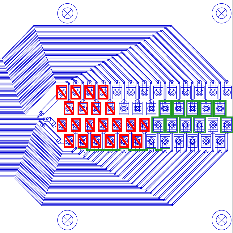
| Use resistor to complete circuit on cold end of the stripline and conduct continuity checks using breakout box. We have lost pins 1-4, 14-17, 26-32 & 44-39 as shown in Fig. 4. These correspond to stripline traces 18-38. If I was a betting man, I'd put a significant amount of money on losing traces 15-17 & 39-41 next. Traces 39 & 41 are the last QET D Return lines and trace 40 is Qo source. Arguably, losing the ability to ground the phonon rails is far more serious than reading out Qo. |
| Figure 4: Stripline pins showing broken ones in red and important ones in green. Only one QET D Return line needs to survive, so they have been indicated by a single green line tied together. |
|---|
 |
| 2330 | Cover bottom of IVC with clean, plastic bag and cogitate on problem overnight. |
|---|