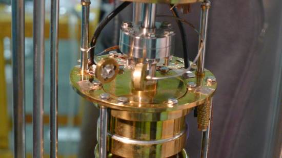
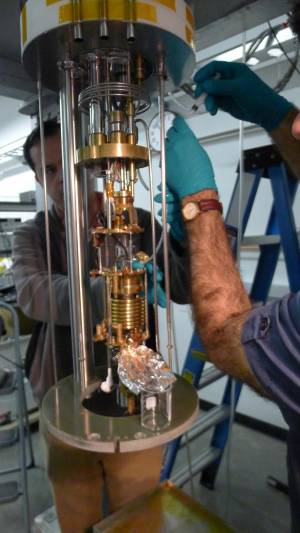
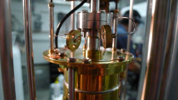
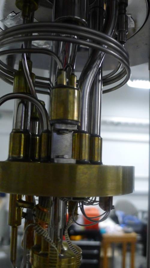
In preparation for the maintenance, the IVC was opened and the fridge cans were removed. At the start of maintenance the fridge looked as it is shown in Fig. 1 below.
| Figure 1 |
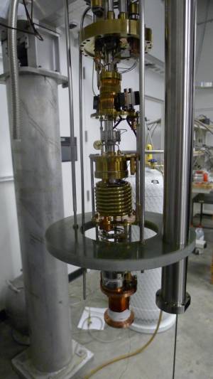 |
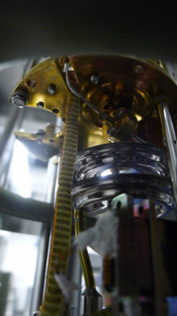
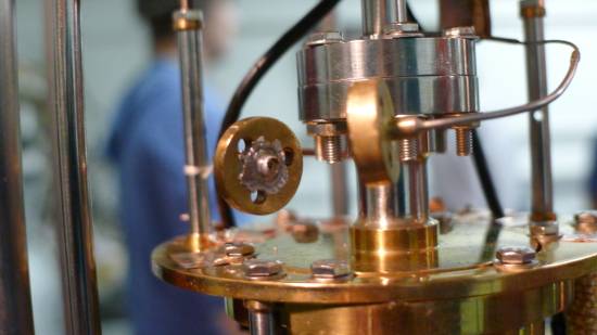
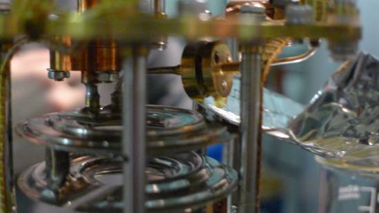
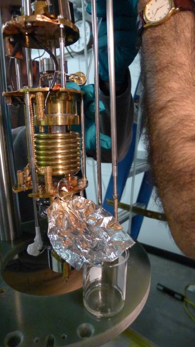
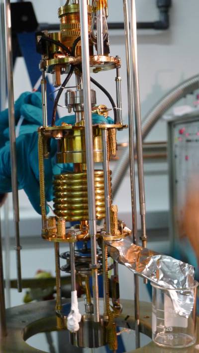
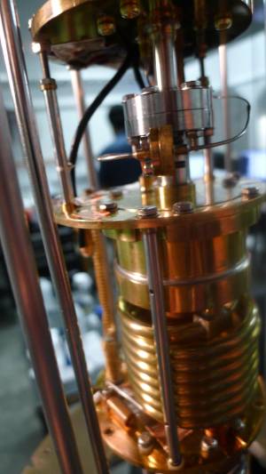
It is important to note the small brass flange near the center of the picture, to the left of the silver flange. This is the first impedance leading down from the condenser side of the fridge through the still and eventually leading to the mixing chamber. Inside of this flange is an impedance wire which slows the flow sufficiently for the mixture to condense. We initially believe that a small amount of oil could be trapped in front of this wire. Once should also note a second impedance flange without an impedance wire, located below the brass plate but before the silver step exchangers. This impedance is more clearly seen in Fig. 2.
| Figure 2 : Second (lower) Impedance |
 |
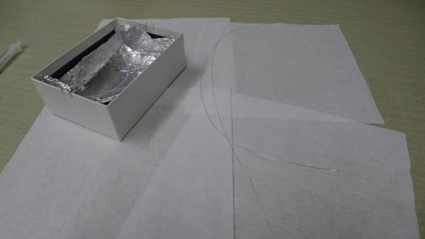
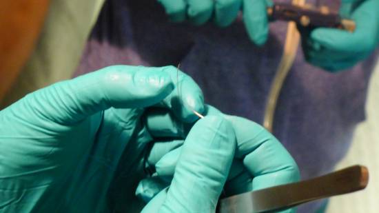
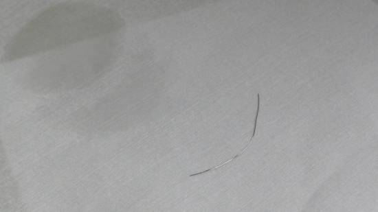
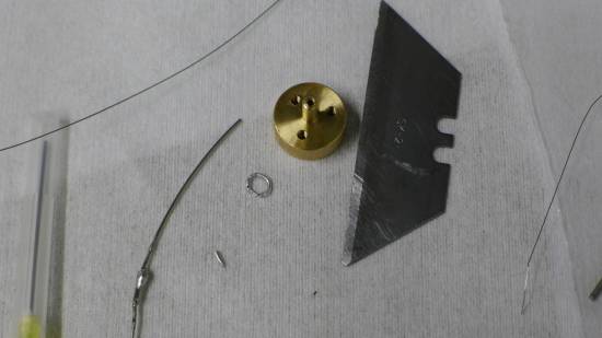
In preparation for a solid blockage (dust, dirt etc.), Nader brought a series of thin wires (shown in Fig. 3) that could be inserted into the impedance flange to dislodge a solid block. These could also be inserted into the flange and then wiped to see if any oil is visible.
| Figure 3 : Nader's supplies to unblock and solid obstruction near impedance |
 |
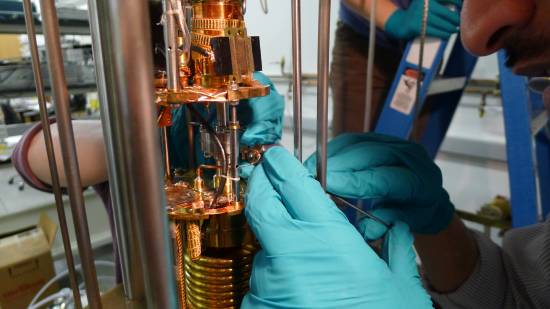
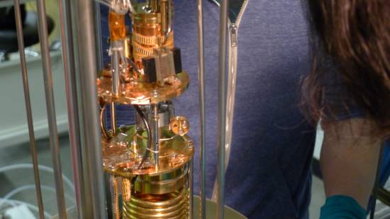
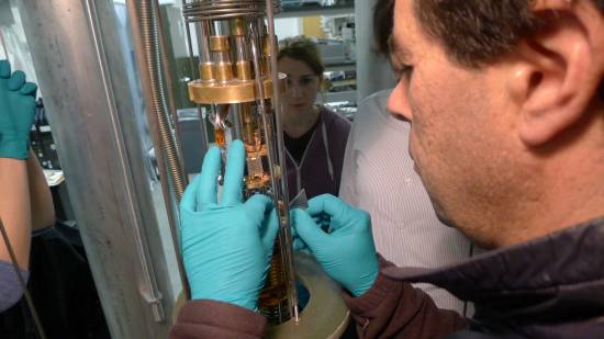
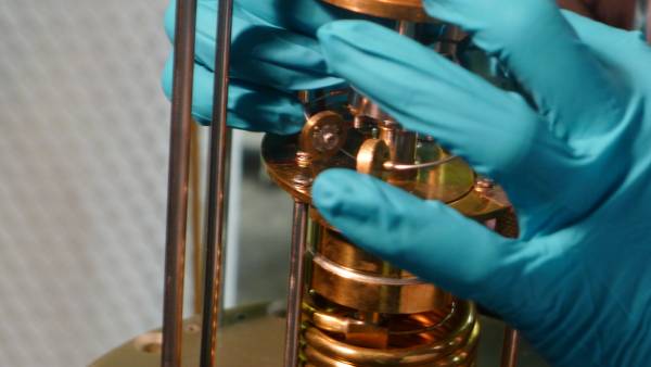
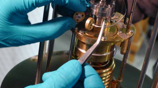
As mentioned above, we initially thought that a blockage would occur near the first impedance, and thus we started by opening this flange. This flange has an indium seal, so once the screws were removed, a razor blade was carefully used to open the flange the rest of the way (opening procedure shown in Fig. 4). Once the flange was opened, the two sides could be gently pulled apart, revealing the impedance wire (shown in Fig. 5. The silver indium can be seen on the opened brass flange). Figure 6 shows the impedance wire being carefully removed from the flange with a pair of tweezers.
| Figure 4 : Opening the first (upper) impedance |
   |
| Figure 5 : First impedance opened. Inner impedance wire shown |
 |
| Figure 6 : Removing the impedance wire |
     |
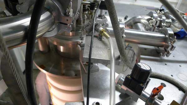
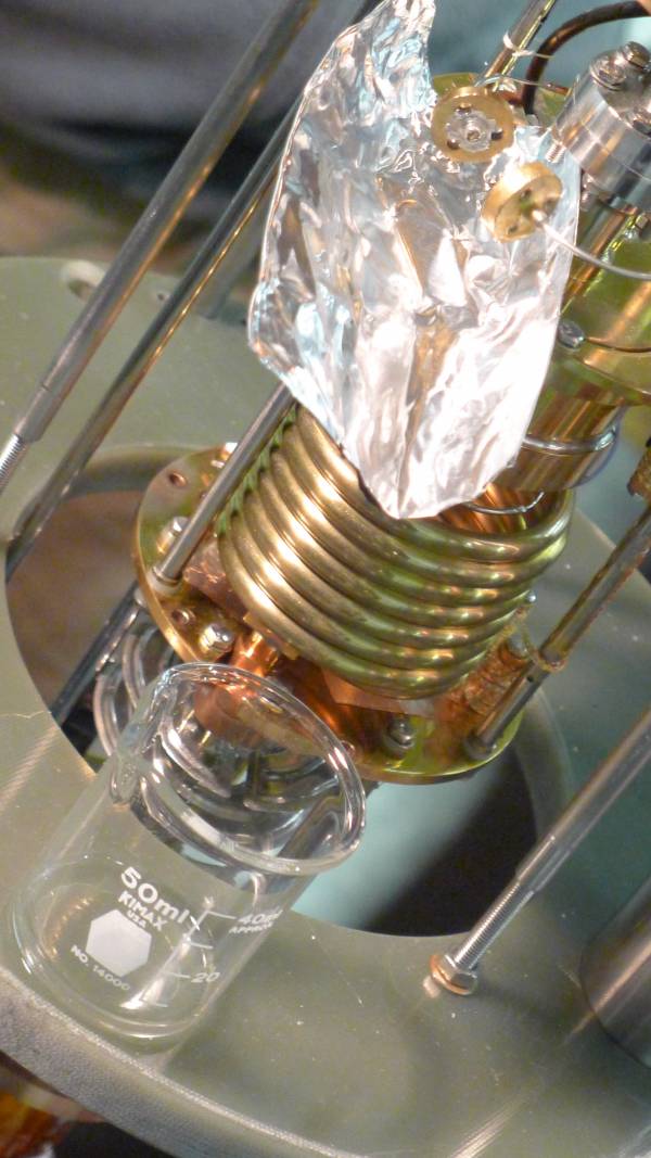
Once the impedance wire has been removed, the flange is checked for flow. The port leading from the condenser side of the fridge to the IGH is opened and a tube leading to a industrial-grade He canister is connected, as shown in Fig. 7. Isopropanol is then sprayed at the flange side connected to the condenser line external port. Bubbles forming in this isopropanol indicate that He gas is flowing through the line; flow has not been blocked. Isopropanol that has been sprayed onto the flange is connected into a glass beaker as shown in Fig. 8. There is no discoloration to this isopropanol, and thus no indication of oil yet. Wiping a wipe on the flange also shows no oil residue.
| Figure 7 : Flushing condenser side with He gas |
 |
| Figure 8 : Isopropanol collected from spraying |
 |
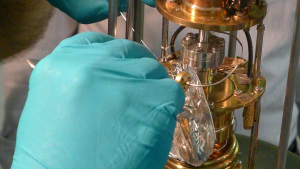
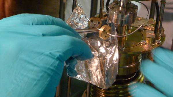
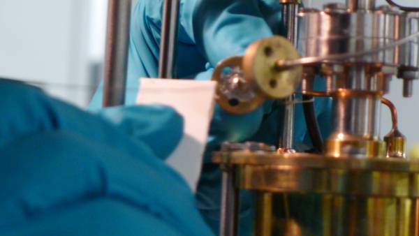
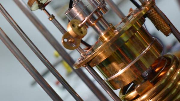
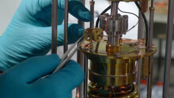
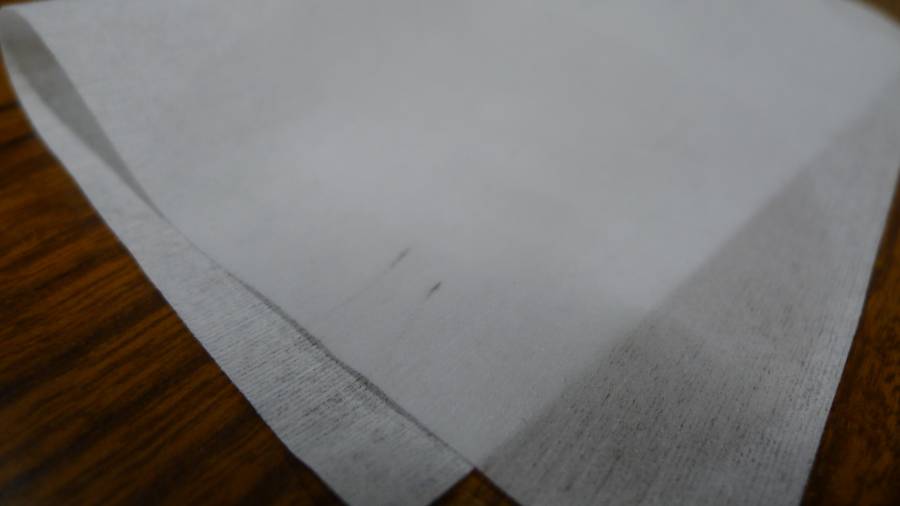
A wire can now be inserted into the impedance flange to dislodge any hard block as well as check for oil. In Fig. 9 a wire is fed into the flange side leading to the external condenser line port. Once the wire is removed from the flange it is wiped with a Kim wipe. Although a faint discoloration of the wipe can be seen, it is too light to be photographed. To reduce the risk of plugging the capillary with indium, excess indium is cleaned from the flange side leading to the mixing chamber before proceeding (as shown in Fig 10.). Indium is removed with isopropanol, a small, pointed, plastic scraping tool, and a Kim wipe. Once the indium has been sufficiently cleared away, a wire can now be inserted into this side of the first impedance flange, shown in Fig. 11. Residue from this wire is seen on the Kim wipe in Fig. 12. This is an indication of oil in the system.
| Figure 9 : Feeding wire through to check for obstruction |
  |
| Figure 10 : Gently cleaning off indium |
  |
| Figure 11 : Feeding wire through other side to check for obstruction |
 |
| Figure 12 : Wire's residue visible on wipe |
 |
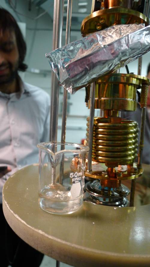
For the next step, acetone is fed down the external condenser line port, and then the gas is used to pressurize the acetone. Once acetone has been fed down the line and flows out of the first impedance flange, it is collected into a glass beaker, shown in Fig. 8. The beaker's acetone was checked for any discoloration. A slight discoloration was noted.
| Figure 13 : Acetone sprayed through condenser line port comes out clear |
 |
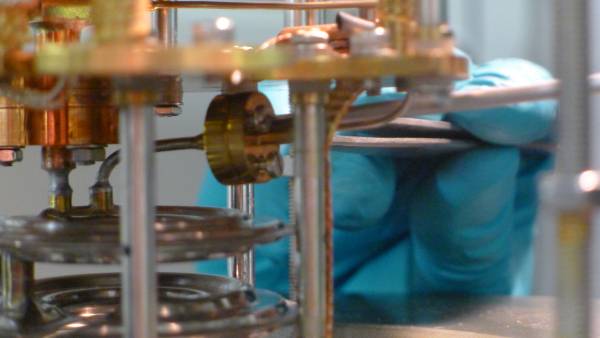
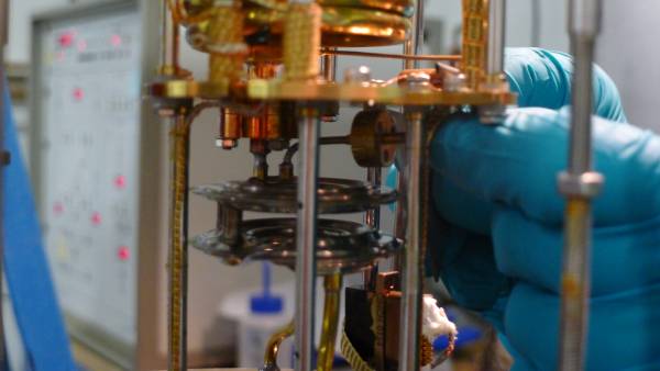
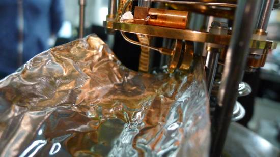
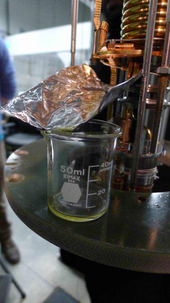
With some indications of oil found in the first impedance, we decided to continue moving downward and open the second impedance. The second impedance was opened using the same method as with the first impedance, demonstrated in Fig. 14. However, the second impedance has no impedance wire, and He gas was added to the system through the still line, instead of the condenser line. Oil was found in the second impedance, and documented in Fig. 15. Oil from this impedance was collected in a glass beaker such that its color could be noted; it was a light gold color.
| Figure 14 : Opening second impedance |
  |
| Figure 15 : Oil from second impedance |
   |
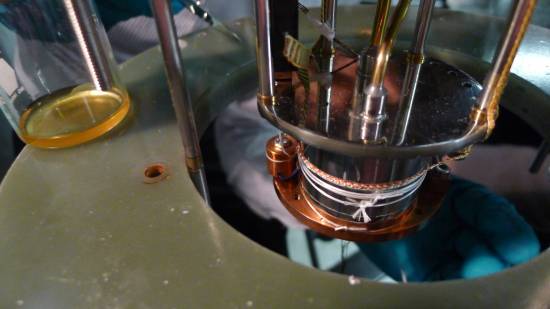
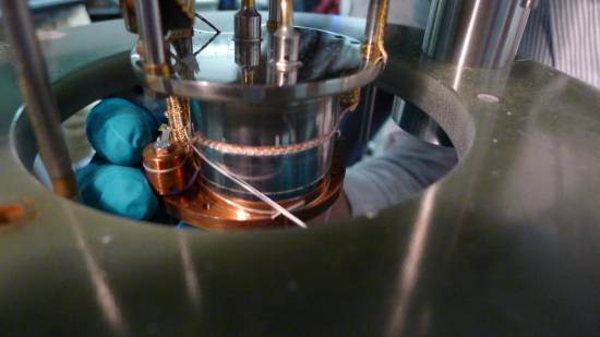
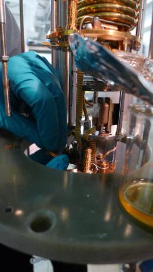
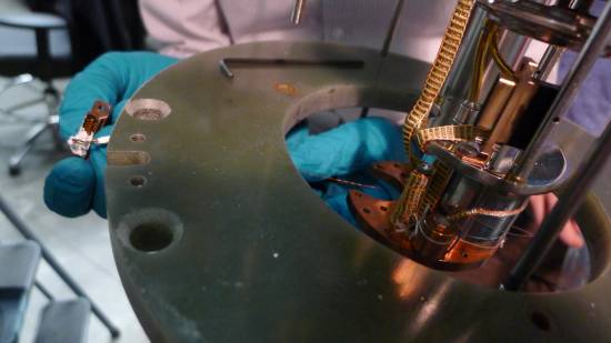
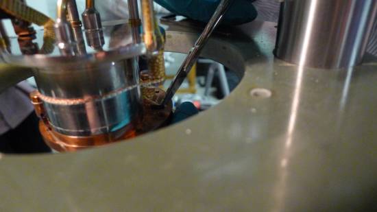
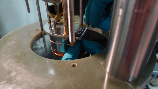
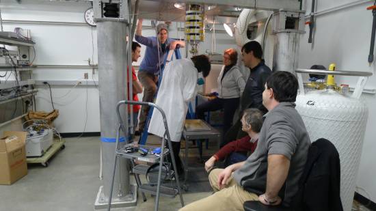
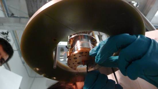
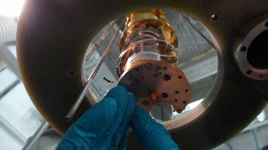
Once oil was discovered in the second impedance but not the first, it was apparent that oil had likely flowed into the fridge through the still line. Thus we proceeded downward to the mixing chamber. Before the mixing chamber could be reached, a series of wires and structures needed to be removed. First, the copper spool holding one of our thermometer wires (located at the bottom of the fridge in Fig 1.) was removed. All thermometry near the mixing chamber was disconnected and/or detached from the system, including the two mixing chamber thermometers and the mixing chamber heater. Wire heat sinking posts were detached from the system as well. The removal of all wires and structures attached to the mixing chamber is documented in Fig. 16. (NOTE (2015/02/06): It appears that during this process, wires to one of the mixing chamber thermometers and the mixing chamber heater were disconnected.) Once the mixing chamber is free of all superfluous connections, the mixing chamber screws are removed and the bottom copper plate of the mixing chamber (Fig. 17).
| Figure 16 : Removing wires to access mixing chamber |
      |
| Figure 17 : Ready to open the mixing chamber. The excitement is palpable |
   |
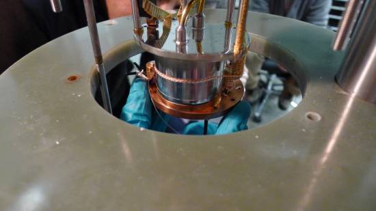
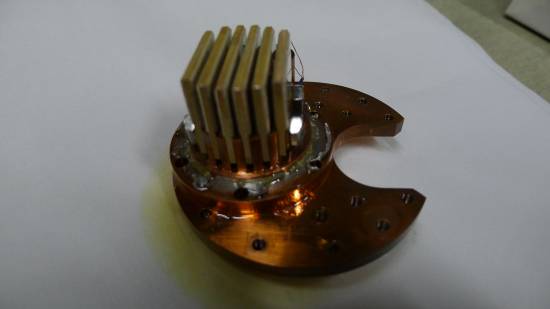
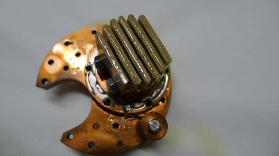
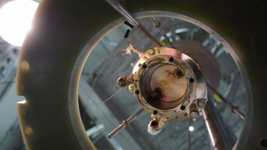
The oil found in the mixing chamber is documented in Fig. 18. Close ups of the lower copper portion of the mixing chamber before it was cleaned are shown in Fig. 19.
| Figure 18 : Oil from mixing chamber |
 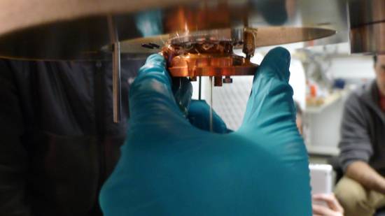 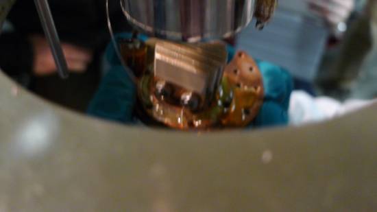 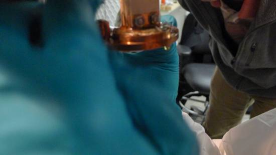 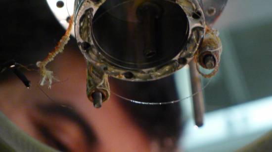 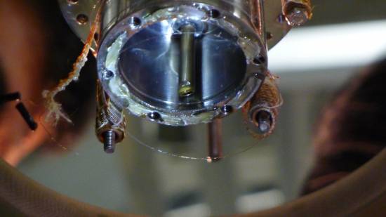  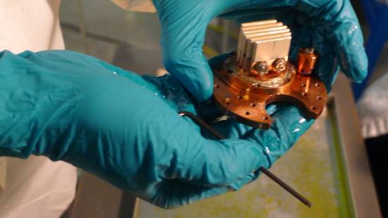 |
| Figure 19 : Close ups of mixing chamber |
   |
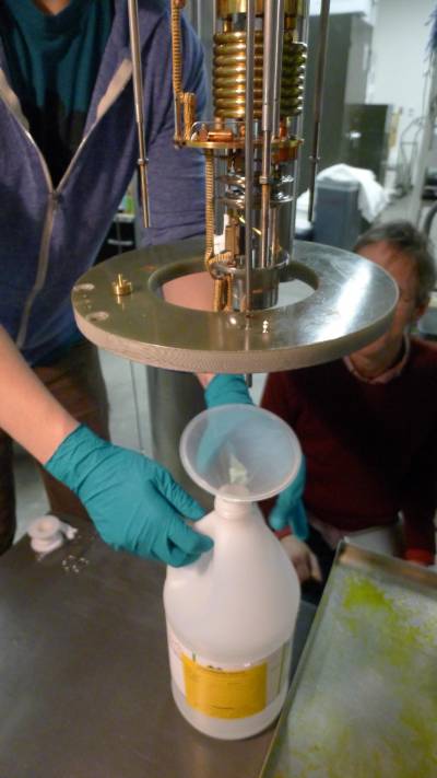
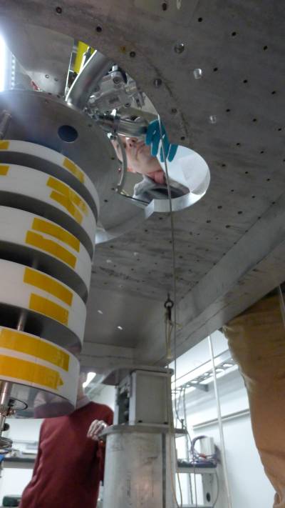
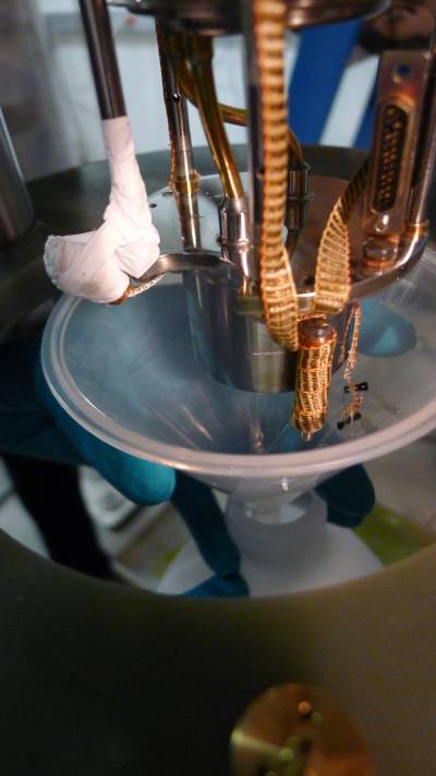
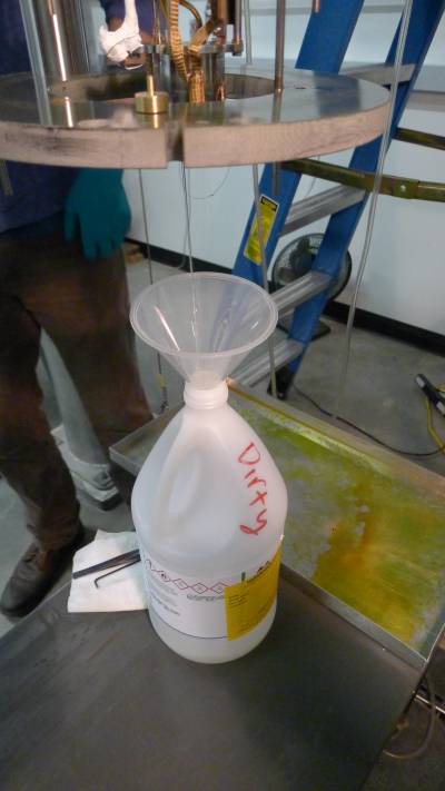
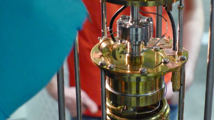
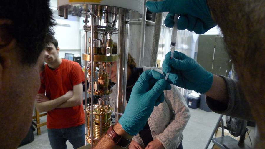
Once the mixing chamber was opened, the still line was cleaned by pouring acetone into the still line port at the top of the fridge and allowing it to flow down, out of the mixing chamber, and into a bottle below. As Fig. 20 shows, discoloration in the acetone indicates the presence of oil. This was done numerous times until the acetone came out clear. Then, a final round of isopropanol was flushed through the still line. A similar method of flushing several times with acetone before a final round of isopropanol was also used on the capillary between the first in second impedance. For this, a copper piece was attached to the first impedance on the mixing chamber side, as shown in Fig. 21. Then plastic tubing was attached to the copper piece such that a syringe could send acetone down through the tubing and into the capillary. This acetone would flow from the first impedance to second impedance and was then collected into a beaker. Once the acetone came out clear, isopropanol was used.
| Figure 20 : Adding acetone to mixing chamber through still line |
    |
| Figure 21 : Add piece to first impedance to squirt liquid from first impedance to second impedance |
     |
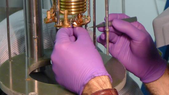
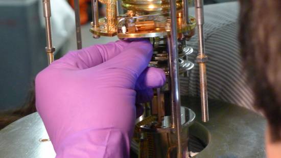
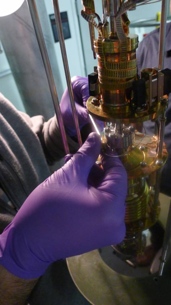
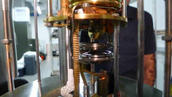
Once the capillary between the two impedances was clean, the second impedance could be resealed, allowing us to clean the capillary between it and the mixing chamber. The impedance flange was cleaned of excess indium, though it's positioning made a thorough cleaning too difficult. The impedance was then resealed with 0.5 mm indium, as shown in Fig. 22. The first impedance was also temporarily resealed (without the use of new indium), to allow us to flush the system with He gas overnight.
| Figure 22 : Using indium ring, reseal second impedance |
     |
| Figure 23 : Temporarily reseal first impedance without indium |
  |
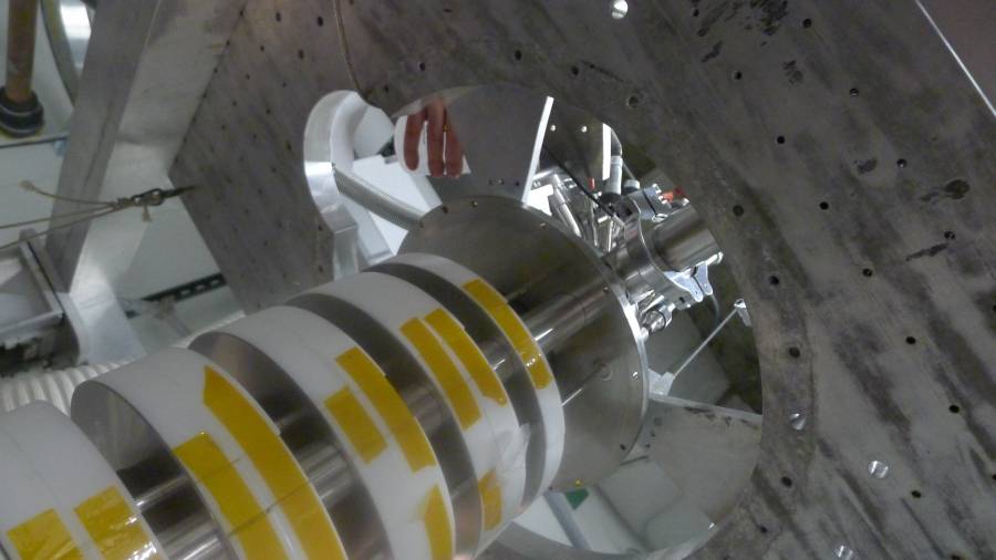
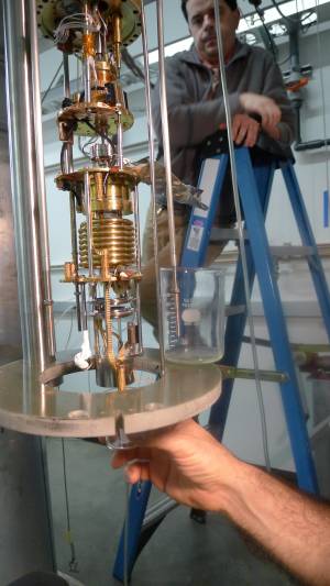
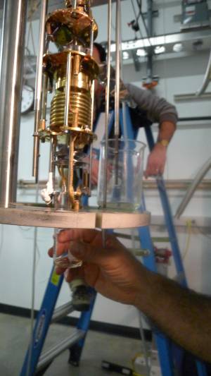
Once both impedances were resealed, acetone was once again poured down the condenser line port at the top of the fridge, and He gas was used to flush out the acetone afterwards. Although the temporary seal of the first impedance proved leaky, acetone still reached the mixing chamber, where it was again collected (see Fig. 24). This was done several times before the end of the night. Then, He gas was hooked up to flush on both the condenser side and still side ports on top of the fridge, flowing to a still open mixing chamber. The fridge was left in this position overnight.
| Figure 24 : Pour acetone down condenser line to reach mixing chamber (leaky first impedance) |
   |
Day two began with a continuation of the cleaning efforts started on Day 1. As with the night before, acetone was flushed through the condenser line port on top of the fridge down through both impedances (the first impedance still leaking through it's temporary reseal), and out through the opened mixing chamber. As some of us continue the fridge line cleaning efforts that involved flushing several rounds of acetone down fridge lines followed by a final round of isopropanol, others began cleaning external portions of the fridge.
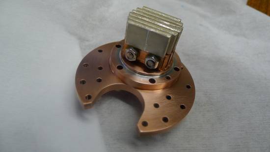
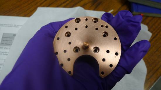
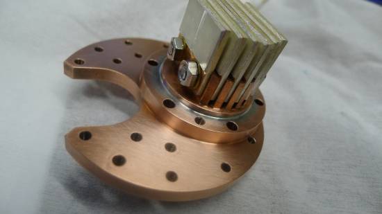
Large bellows and pipes leading from the fridge to the IGH/pump system and back were found to smell oily. Thus, bellows and valves used in the circulation lines were cleaned with two rounds of acetone followed by a round of isopropanol. The still line pipe that was fixed into the wall was scrubbed with acetone (and later isopropanol) soaked wipes. The lower copper portion of the mixing chamber was polished and cleaned with acetone and isopropanol, as shown in Fig 25. Once the cleaning was complete, the mixing chamber was sprayed with N2 gas from the LN2 dewar to remove and potential threads left over from the wipes.
| Figure 25 : Polished and cleaned mixing chamber |
   |
| Figure 26 : Installing mixing chamber with indium seal |
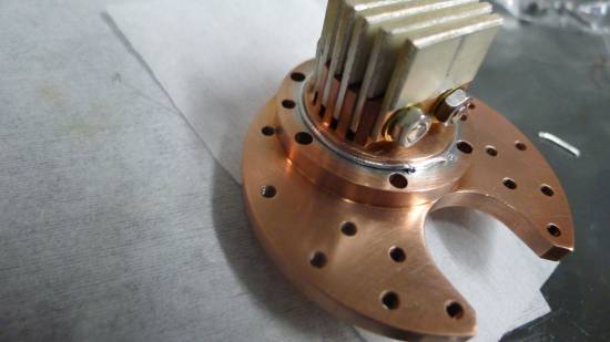 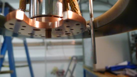 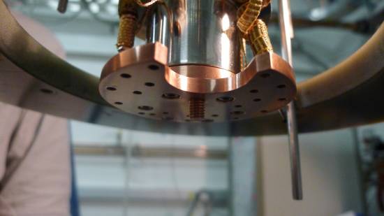 |
Once cleaning of the mixing chamber and fridge lines was completed, the mixing chamber was reinstalled using 1 mm indium. The process of installation is shown in Fig. 26. Following this, the first impedance flange was also resealed, after the impedance wire was replaced. All three indium seals were allowed to set for a few days before the screws were tightened, to allow for the indium to flow. With all three indium seals completed, it was possible to check for room temperature throughput. Unfortunately, when He gas was added to the fridge through the still line, no gas was seen on the condenser line side. It was decided that this was either due to 1) acetone still in parts of the fridge, inhibiting flow, 2) a hard blockage (indium?) that we formed in the fridge, or 3) further oil trapped in the fridge. The easiest to test for and solve was acetone.
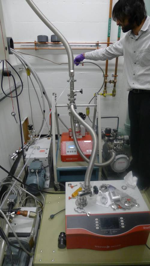
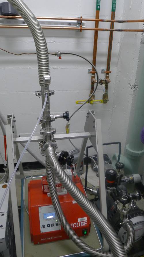
Thus, the pumping was set up such that the scroll pump, turbo pump and leak checker could all be used on either the still line side or condenser line side. The still line was disconnected from the He-4 pump intake/exhaust lines and connected to top of turbo pump structure. The copper condenser pipe was disconnected from the He cold trap and connected directly to condenser line port. The other end of copper condenser pipe was disconnected from the back of IGH and passed through the wall to pump room. Clean 16K bellows were used to connect the copper pipe to the scroll pump apparatus. The external pressure sensor was connected to copper condenser pipe/scroll pump apparatus, and the He gas line was connected to the turbo pump structure. This pumping setup can be seen in Fig. 27.
| Figure 27 : Pumping apparatus to pump acetone and isopropanol from fridge lines |
  |
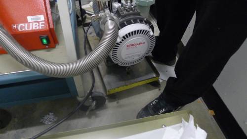
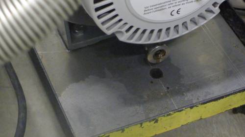
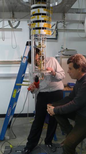
Due to setting up pumping system, all portions of system were at atmosphere, and thus needed to be pumped out. During this, we noticed that acetone was coming out of the scroll pump exhaust, and it was discolored with oil (Fig. 28). We also noticed that these lines had begun freezing, as they still contained acetone. We then carefully used the heat gun to remove acetone and pump down the lines, as shown in Fig. 29. Once the external pressure sensor read below 0.1 mbar, we opened the valve to the condenser side of the fridge and started pumping with scroll pump (with gate valve open). After several minutes (and more acetone heating in the fridge lines) we noted that the external pressure sensor had stabilized at 1.2E-1 mbar. We then closed the gate valve (and thus isolated the large copper still pipe), which lowered the external pressure sensor below E-2 mbar. This is an indication of throughput. We then started pumping on still line side to reduce this pressure. Once the pressure dropped below E-2 mbar and all noticeable acetone has been heated out of the system, we switched to pumping on condenser side once again, with the gate valve open; the external pressure sensor stabilized at roughly E-2 mbar, but was slowly dropping. We then commenced pumping on both sides of fridge, and switched to turbo pump to leave overnight.
| Figure 28 : Oil and acetone seen coming out of scroll pump exhaust |
  |
| Figure 29 : Use heat gun to warm acetone from fridge lines and traps and pump out |
  |
Overnight the external pressure sensor reached down to 5.4E-3 mbar (this might be lower, since this gauge tends to get stuck). We started the morning by isolating the turbo pump, and we saw no immediate change in external pressure sensors. After several minutes without change in the pressure, we turned on the leak checker. We started the leak check with a test of the pumping room manifolds, with a background leak rate of 8.8E-8 mbarL/s. Although some occasional spikes up to 9.3E-8 mbarL/s were seen, these spikes were non-repeatable. With no indication of pumping manifold leaks, we raised and pumped out the fridge dewar. We then purged the dewar with He gas while the fridge lines were open and connected to the leak checker. The leak tested started with a background rate of 1.8E-7 mbarL/s, and no obvious rise or spike in leak rate was observed; thus no leak was detected.
We then began pumping on the condenser and still line with the turbo pump. After an hour of pumping on the lines, we added He gas to the still line to check throughput to the condenser side. As soon as the gas was added to the still line, a change in pressure was registered on the condenser line side, indicating a good throughput. However, since this was not accurately measurable, we couldn't compare it to previous tests. Thus we turbo pumped on the fridge lines for another two hours. Once the lines were sufficiently pumped out we isolated the fridge lines (closed gate and condenser line valves) and returned the external circulation lines/bellows to their standard positions. We then continued pumping on the entire system for another hour.
After the pressures were sufficiently low (P1<100 ubar), we performed a throughput test with the standard setup. We added He gas to both the condenser and still line side (keeping V7, V2 and V3 open) until G1 reads 570 mbar. P1 cannot be used as an accurate gauge at these high pressures and as expected read 1000 mbar. We then performed the throughput test by closing V2 and V3 to isolate the still and condenser line sides, and then opening V1 (without pumping out G1 before hand). G1 dropped to 46 mbar and then began to rise at a rate of (on average) 7 mbar/min. This compares nicely to our usual room temperature throughput rate of 6 mbar/min.
With a successful throughput test confirming no room temperature blockage. we commenced pumping out of fridge lines with the scroll pump. Once low enough, we switched to turbo pump and left overnight.