1D Source Mover Notes
The 1D source mover has 6 wires in total. 2 wires for Coil1, 2 wires for Coil2 and 2 wires for Near and Far endstops.
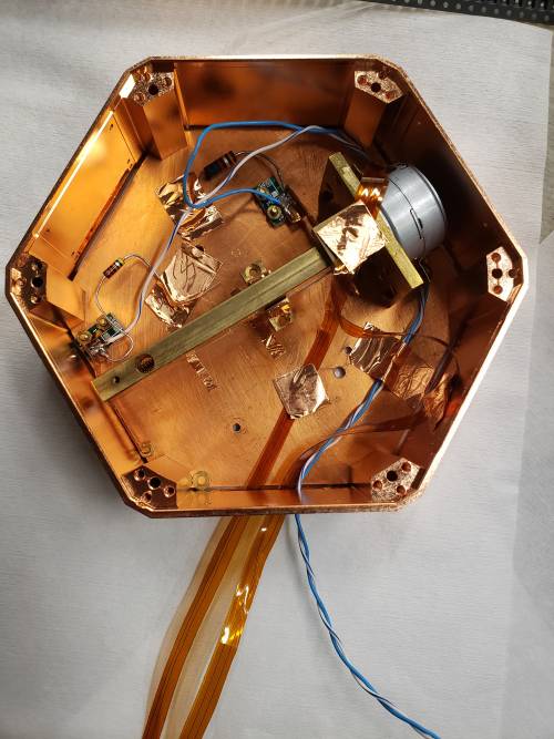
In Run 78, the channel mapping for these wires are as follows: Refer page: Link to Run 72 wiring
| Run 78 accessory wiring | ||||||||||||||||
|---|---|---|---|---|---|---|---|---|---|---|---|---|---|---|---|---|
| accessory | Motor Coil 1a | Motor Coil 1b | Motor Coil 2a | Motor Coil 2b | near endstop | far endstop | (screw term1) | Thermometer P1 | Thermometer P2(electrode1) | Thermometer P3(screw term2) | Thermometer P4 | |||||
| acc wire | Motor Coil 1 | Motor Coil 2 | ||||||||||||||
| Tower F4 | 1 | 2 | 3 | 4 | 5 | 6 | 7 | 8 | 9 | 10 | 11 | 12 | 13 | 14 | 15 | 16 |
| interposer conns | brn | w brn | org | w org | blu | w blu | grn | blk | blk | pur | pur | |||||
| no soc | no soc | no soc | no soc | no soc | no soc | no soc | no soc | no soc | ||||||||
| stripline | 49 | 50 | 8 | 9 | 11 | 12 | 13 open | 45 | 2 | 46 | ||||||
| label | pBr3 | pBr4 | pCr3 | pCr4 | pAr3 | pAr4 | pAr5 | pDr3 | pAr1 | pDr4 | ||||||
| STRIPLINE ## | ||||||||||||||||
| CABLE # | ||||||||||||||||
| stripline D50 | 36 | 18 | 8 | 23 | 4 | 19 | 1 | 41 | 17 | 40 | ||||||
| DCRC/diverter Dsub | 48 | 33 | 10 | 28 | 14 | 32 | 17 | 43 | 1 | 44 | ||||||
| Dsub diverter board | U09-2 | U10-3 | U06-3 | U07-3 | U08-4 | U09-1 | U10-4 | U06-4 | U01-4 | U07-5 | ||||||
On the warm side, there is a diverter board which take the connections of the motor coils and endstops out of the I/O cable connection. The four wires on the top portion of this picture are the motor coil wires and the blue bunch is taking away the endstop connections to the breakout box region.
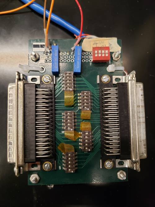
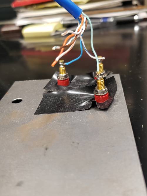
The four motor wires are further connected to the breadboard which has the Arduino UNO and driver stacked together. The 4 wires are connected to the 4 slots in the bunch of capacitors that you can see on the breadboard.
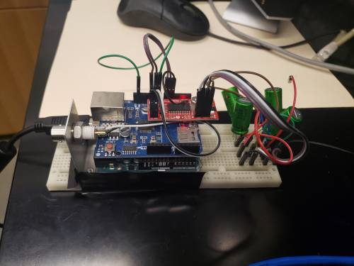
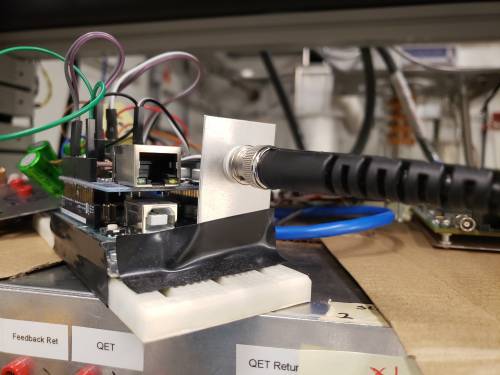
The arduino is connected through BNC cable to gwINSTEK power supply. We can use Ch1 and turn the voltage up till 7.1 V during operation.
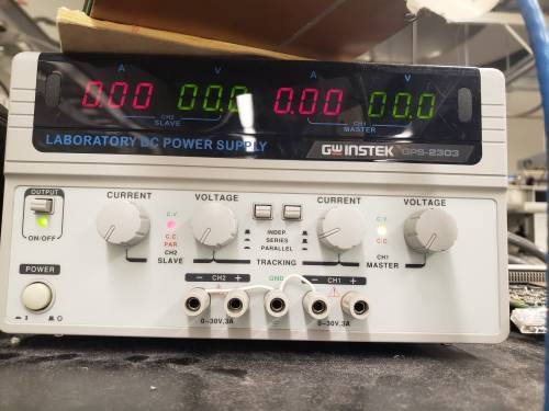
The power supply slot on the arduino is shown below. Other than this slot, we use the USB connection slot to talk to the arduino from the fridge computer.