Quantum Efficiency Measurement Procedure
The general monochromator procedure should be followed, with some changes.
| QE Setup |
|---|
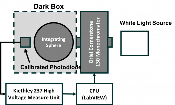 |
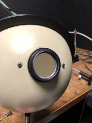
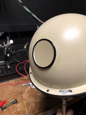
The integrating sphere should be placed between the monochromator output and the photodiode to uniformly distribute light across the opening. This is a big tan sphere with Oriel written on it. This allows for area corrections to be done. Make sure the side with the pegs and insert are facing the monochromator.
| Integrating Sphere | |
|---|---|
| This side connects to monochromator output | PMT or photodiode should be flush with hole on this side |
 |  |
Take a spectrum of the white light source with the photodiode. Without turning off the light source or bumping anything, replace the photodiode with the PMT. Disconnect the photodiode from the Kiethley unit. Using a triax-to-BNC adapter, connect the signal line of the PMT to the Kiethley unit. Bias the PMT to the desired voltage. In the “GoTo Wavelength Loop-Step” program, change the “Pwr Spectrum” field to the data file of the spectrum that was taken with the photodiode. Change the reference sensor field to “Pwr Spectrum”. The output of this data file will be a value that needs to be divided by the gain and then multiplied by the area of photodiode (1 cm^2) and divided by the area of the PMT (20.27 cm^2) to obtain a responsivity in units of Amperes per Watt (see my senior thesis).
From this responsivity, the QE can be calculated. See the veto paper or my thesis to see how this calculation is done. Hamamatsu also has the calculation in their PMT Handbook.