Revised NaI Detector Shielding
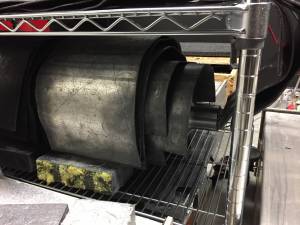
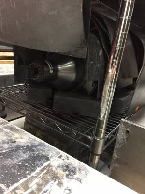
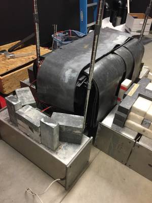
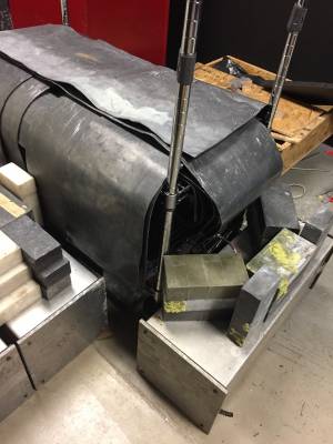
Moving on from the last shield configuration (Shield 5), quite a bit more lead was obtained with the help of Hannah. In particular, shielding by the PMTs were significantly increased. More sheets hanging over the rack was also added.
| Shield 6 | ||
|---|---|---|
| Figure 1: Interior of shield | Figure 2: Interior of shield | Figure 3: Exterior of shield |
 |  |  |
| Figure 4: Exterior of shield | Figure 5: Exterior of shield | Figure 6: Exterior of shield |
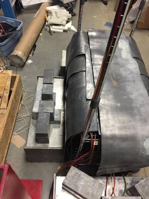 |  | 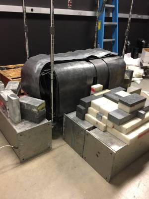 |
| Poly shown in Figure 6 composes the collimator to house the Cf-252 source. | ||
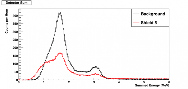
| Figure 7: Comparing shield 5 and background |
|---|
 |
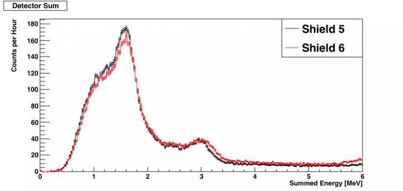
| Figure 8: Comparing shield 6 and shield 5 |
|---|
 |
In Figure 7, only the peak amplitudes should be compared. A different discriminator with lower thresholds was used for the Shield 5 and Shield 6 run. Higher thresholds were used for the “Background” run due to the availability of equipment.
No appreciable difference can be seen between Shield 5 and the the revamped shield (Shield 6). This is despite there being roughly double the lead on the sides and much more lead surrounding the PMTs. I am not sure why no improvements were observed. Where should we go from here?
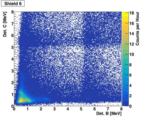
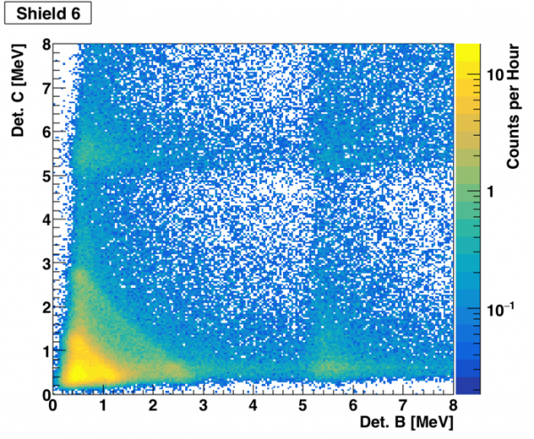
What would sources of the coincident background be? Coincidence plots for the Shield 6 run are shown in Figures 9 and 10.
| Figure 9: Shield 6 Coincidence Plot | Figure 10: Shield 6 Coincidence Log Plot |
|---|---|
 |  |