−Table of Contents
NaI Detector Characterization
Introduction
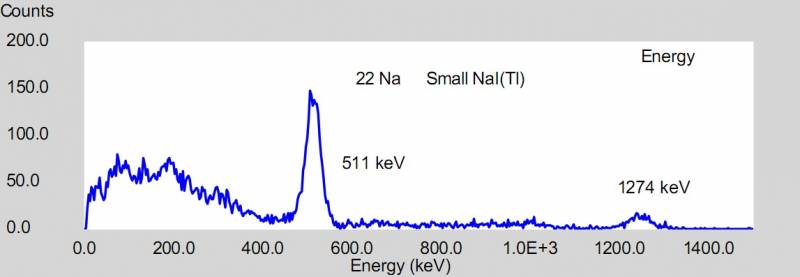
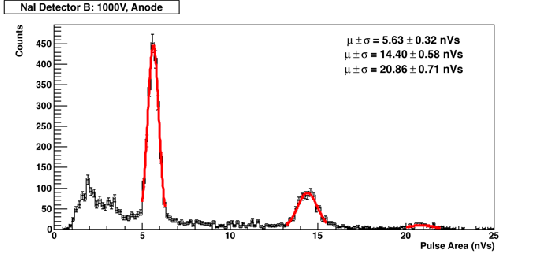
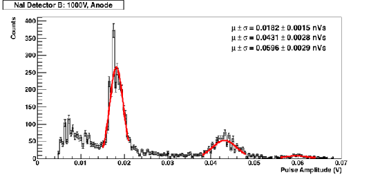
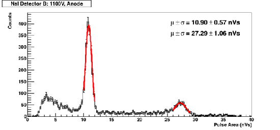
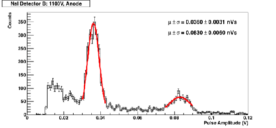
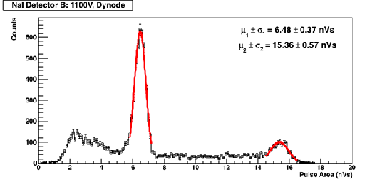
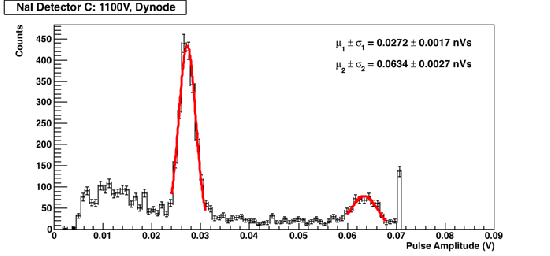
A Na-22 gamma source was placed underneath the NaI detector. Biases of +1000V and +1100V were applied to the Ortec 266 PMT (make sure it's a positive bias!!). The signals of the anode (negative pulses) and dynode (positive pulses) were examined.
| Figure 1: Na-22 Gamma Spectrum |
|---|
 |
| http://teacher.pas.rochester.edu/LUX/Electronics/DDC-8/DDC-8.html |
Data
Detector B
| Figure 2: Pulse Area | Figure 3: Pulse Amplitude |
|---|---|
 |  |
| Figure 4: Pulse Area | Figure 5: Pulse Amplitude |
 |  |
| Figure 6: Pulse Area | Figure 7: Pulse Amplitude |
|---|---|
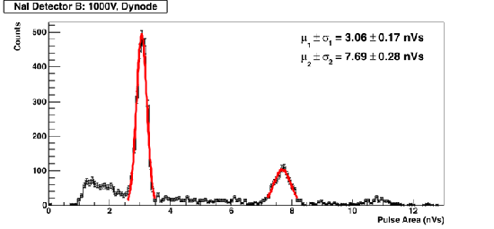 | 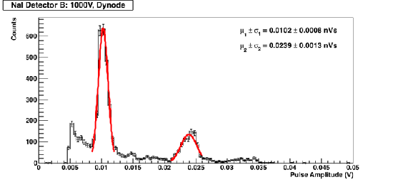 |
| Figure 8: Pulse Area | Figure 9: Pulse Amplitude |
 | 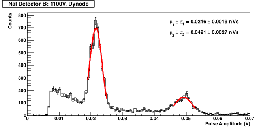 |
Detector C
| Figure 10: Pulse Area | Figure 11: Pulse Amplitude |
|---|---|
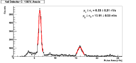 | 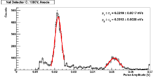 |
| Figure 12: Pulse Area | Figure 13: Pulse Amplitude |
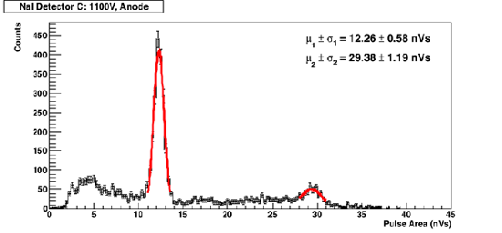 | 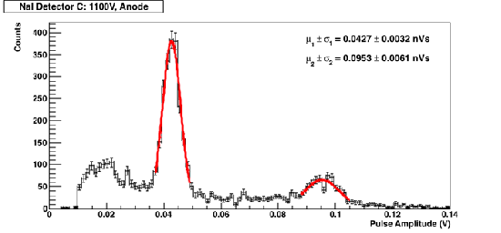 |
| Figure 14: Pulse Area | Figure 15: Pulse Amplitude |
|---|---|
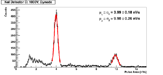 | 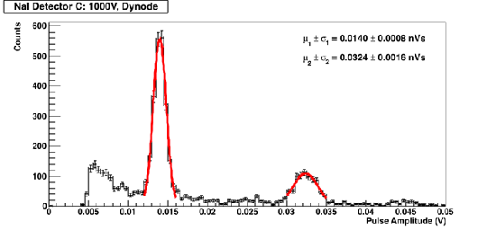 |
| Figure 16: Pulse Area | Figure 17: Pulse Amplitude |
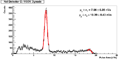 |  |
Analysis
| Table 1: Summary of Results (Area Analysis) | |||||
|---|---|---|---|---|---|
| Detector | Bias (V) | Output | 511 keV Peak (nVs) | 1.274 MeV Peak (nVs) | Full Width at Half Max (nsec) |
| B | 1000 | dynode | 3.06 | 7.69 | 248 |
| C | 1000 | dynode | 3.99 | 9.90 | 235 |
| B | 1100 | dynode | 6.48 | 15.36 | 243 |
| C | 1100 | dynode | 7.96 | 18.39 | 236 |
| B | 1000 | anode | 5.63 | 14.4 | 270 |
| C | 1000 | anode | 6.33 | 15.91 | 256 |
| B | 1100 | anode | 10.90 | 27.29 | 252 |
| C | 1100 | anode | 12.26 | 29.38 | 238 |