This page shows the steps involved in creating a L1 trigger for a RevE DCRC.
We start with the psds from each channel of the detector and a pulse template taken from laser data (triggering on laser pulses). For testing we will be working primarily with the NF-C detector and its channels which are labeled PES2 and PFS2.
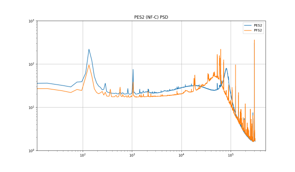
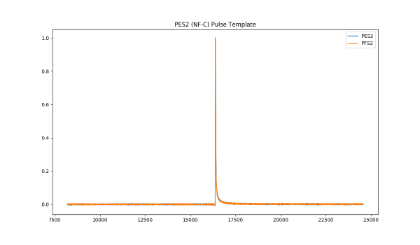
These are input into the trigsim python package, which can output multiple sets of FIR coefficients for the L1 trigger. Currently I am considering 3 detectors (R1, NF-H and NF-C) each with two channels combining to 3 sets of FIR coefficients.
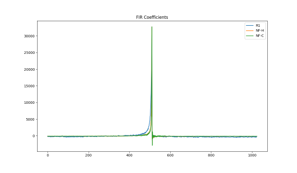
We can test these coefficients by again using trigsim with a test pulse. Using a pulse form the NF-C data (left) results in a spike like we expect (right).
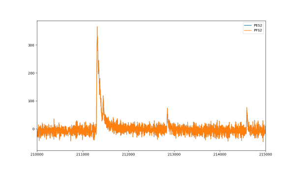
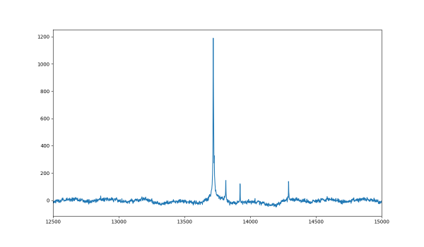
After the right plot is generated, it must pass a threshold in order to activate the trigger. This threshold is typically a multiple of the resolution, but trigsim calculates the resolution as 1126.34, which is much too large compared to what we see on the right plot (below 100).