2021/09/03 (Friday)
- Lab in-personnel: Matt and Giulia
| Status | Run 74 in progress. First cooldown after IVC rebuild. |
|---|---|
| Tower thermometer is reading high, probably this is a thermometer problem and the actual temperature is much lower. High noise in some of the charge channels. | |
| Setup: DIB1/2+acc → SL 41/43 → 3.2 MHz filters → cables 2/3 → nothing/Source_mover_board+HV_diverter_board → DCRC50(3)/55(1). Kepco 40V supplye → HV BNC. Lead shield erected, 4 walls. Currently both DCRCs are on. | |
| Position of Am source: y = 0.0 mm | |
| 0837 | Tower/MC/Coldplate = 165.2/35.9/192.8 mK, Still = 1.41 K / 0.070 mbar / 0 mW, G1/G2= 287.1/264.5 mbar, 1K Pot = 1.56 K / 10±1 mbar. MB = 74.9%. |
| 0842 | Couldn't fill LN2 cold trap bath even if the dewar doesn't seem empty. |
| 0848 | At 10kHz noise in DCRC3qI/qO/DCRC1qI/qO = 19/4.3/3.7/92 8e-6. This is q3/q1/q4/q2 At 3kHz (peak) noise in DCRC3qI/qO/DCRC1qI/qO = 470/44/43/1000 e-6 |
| Noise is slightly lower than yesterday. | |
| 0858 | Start 45 min series of 10V/0V (bias applied after 60 sec), with 1000 beginning randoms, trigger threshold 100/50/60/300 on DCRC3qI/qO/DCRC1qI/qO, 5Hz in-run randoms, with 1.6384 ms pulses (8192 length) and 400 us prepulse (500 length). Use Sequencer script r74_takeandflash_dcrcbias.msl. I stoped it because it was still triggering and applied the flash for 10 min. |
| Sequence aborted early due to overtriggering | |
| Let's try a series with the DCRC3 FETs turned off. The idea is that this will decrease the amount of IR background. We'll see whether that has any effect on the pattern in q4. | |
| 1310 | Confirm that turning off DCRC3 15V power changes the waveforms significantly in DCRC3. Overall noise decreases but waveforms look choppy. Pretty sure this means the FETs are off. |
| 1320 | Tried a series with DCRC3 FETs turned off, but when the 10V bias was applied to Side 1 there was breakdown noise. Maybe with the 15VDC power off, DCRC3 biasing doesn't work. So… we can still do this test but we'd want to bias Side 2 rather than Side 1. |
| 1320 | Set biases to zero and Flash DCRC1&3 LEDs for 60 seconds. |
| 1345 | Start 47 min series of 0/-10V (bias applied after 60 sec), with DCRC3 FETs turned off, with 1000 beginning randoms, trigger threshold none/none/50/350 on DCRC3qI/qO/DCRC1qI/qO, 5Hz in-run randoms, with 1.6384 ms pulses (8192 length) and 400 us prepulse (500 length). Start sequence with Start button. |
| 1435 | Dial bias down to 0V and flash DCRC1&3 LEDs for 2 minutes |
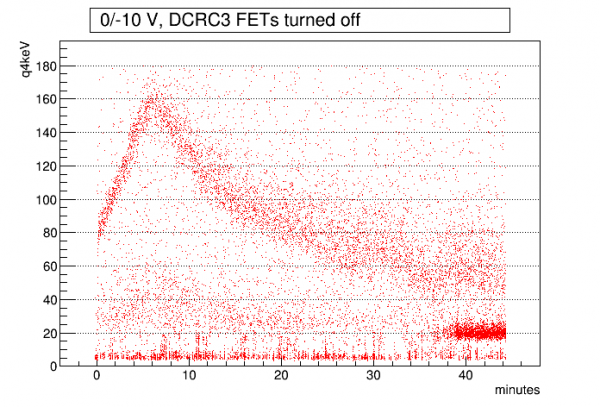 |
| 07210903_1345. Interesting - significantly stronger impact ionization with DCRC3 LEDs off. We should try another one with FETs on. |
| 1445 | Fill LN2 cold trap bath again, after filling LN2 Dewar |
|---|---|
| 1531 | Begin LHe transfer @ MB = 33.6% |
| 1627 | Start 45 min series of 0/-10V (bias applied after 60 sec), with 1000 beginning randoms, trigger threshold 40/30/35/150 on DCRC3qI/qO/DCRC1qI/qO, 5Hz in-run randoms, with 1.6384 ms pulses (8192 length) and 400 us prepulse (500 length). Start sequence with Start button. |
| Dial bias down to 0V and flash DCRC1&3 LEDs for 1 minute |
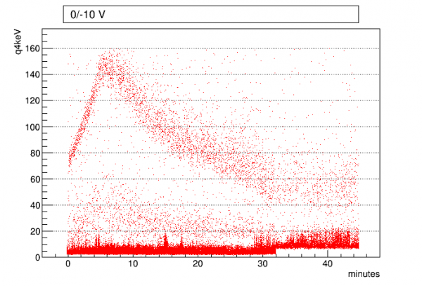 |
| 07210903_1627. Well this is almost as high as the last one. So either it's been pushed into another state, or the 0/-10V bias is producing stronger i.i. than the +10/0V bias. |