2021/03/12 (Friday)
- Lab in-person: Derek
- Virtual partner: Matt
| Status | Run 74 in progress. Investigating whether we can connect to Side2. Currently trying to ground Side 2 via breakout box. |
|---|---|
| Setup: DIB1/2+acc → SL 41/43 → 3.2 MHz filters → cables 2/3 → nothing/nothing → DCRC50(3)/ |
|
| 1058 | MB = 65.7% |
| 1115 | Tower = 88.9 mK |
| The plan later today is to try taking data with bias applied to Side2 from the Kepco supply via the breakout box. We'll also ground the two channels connected to the breakout box (that's q4 and q2 from DIB2) with cables connecting them to the DSub shell. To be certain that we are applying a bias, we should first take data with 0V applied. Then maybe we can crank it up to 15V or something. |
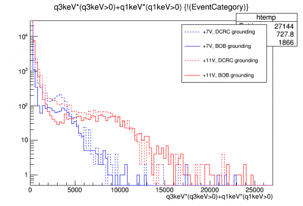
- This plot compares two Side2 grounding schemes - directly connecting Cable 3 to the DCRC versus connecting it to the breakout box and using a ground line to the DCRC Dsub. We show the high-energy spectrum (muons) for DCRC biases of +7V and +11V.
- The sum of q3 and q1 energies are shown, since these are the only two channels connected in the second setup.
- note that some differences may be expected just from the new setup. First, q4(center) and q2(second from outermost) are left floating. So the field may be a little different, but not much I think. Second, if there are electronic crosstalk events, you won't see the crosstalk events from the disconnected channels that you would otherwise see. Third, since we are only triggering on one DCRC in the new setup, you may lose some of the double-trigger events we suspect we are getting in the 2-DCRC setup.
- The basic observation is that the new grounding scheme with the breakout box does not seem to have increased the amplitudes as compared to the direct-to-DCRC setup. (And recall that the direct-to-DCRC setup looked no different from the leave-Side2-floating setup.)
| 1433 | Derek enters lab. |
|---|---|
| 1435 | Tower/MC/Coldplate = 88.3/34.7/183 mK, Still = 1.42 K / 0.130 mbar / 0 mW, G1/G2 = 380/334 mbar, 1K Pot = 1.69 K / 45±2 mbar. |
| 1438 | Fill LN2 cold trap bath. |
| 1450 | Connect qI from BOB (q4) to DCRC3 DSub ground. Connect 0-40V Kepco supply (bias set to 0V) to Side2 and to Dsub ground, negative side on Side 2. |
| Setup: DIB1/2+acc → SL 41/43 → 3.2 MHz filters → cables 2/3 → DCRC50(3)/breakout box. DCRC55(1) → minibob q4 → DCRC3 Dsub ground (via breakout box) Kepco 0-40V supply: Neg → Side2 (via breakout box); Pos → DCRC3 Dsub ground |
|
| 1454 | Start 18min series of 0V data, setup as above, with 1000 beginning randoms, trigger threshold 500/400 on DCRC3qI/qO, 1Hz in-run randoms, with 1.6384 ms pulses (8192 length) and 400 us prepulse (500 length). Start manually with the “start” button. |
| 1456 | MB = 59.5% |
| 1510 | Turn off in-run randoms. Getting a fair amount of noise triggers. Increase trigger thresholds → 600/500. Now triggers are pretty infrequent, <1Hz. The triggers look like sharp glitches rather than real pulses. |
| 1517 | Start 46min series of 0V/-15V data (bias applied after 1 min, last 6 min at 0V), setup as above, with 1000 beginning randoms, trigger threshold 600/500 on DCRC3qI/qO, no in-run randoms, with 1.6384 ms pulses (8192 length) and 400 us prepulse (500 length). Start manually with the “start” button. |
| It was very clear that when HV was raised to 15V, the trigger rate increased and we started seeing real pulses. | |
| 1557 | Turn down voltage to zero. |
| 1603 | Stop data and begin flash. |
| 1606 | Derek leaves lab. |
| Looking at this data later, the q1+q3 high-energy spectrum looks similar to the +11V case in the figure above. |
Todo list for tomorrow:
- With Cable 3 still plugged into the breakout box, check for shorts from Side2, qI Bias, and qO Bias to ground. Should be < 1 nS.
- Power down DCRC1, disconnect it from minibob, then plug Cable 3 into the HV diverter board and into DCRC1. (We'll skip the source mover board just in case that one was introducing problems.) Power up DCRC1 again.
- Try biasing Side2 with the Kepco supply like we did today, but this time using the HV BNC on the diverter board. Last time we tried that we got catastrophic noise - maybe this time will be ok…