| | Overnight bake. |
| 0741 | Tower temp = 176 mK |
| 0743 | End bake. |
| 0943 | Tower/MC/Coldplate = 75.7/61/378 mK, Still = 1.11 K / 0.150 mbar, G1/G2 = 138/126 mbar, 1K Pot = 1.67 K / 50 mbar. MB = 21.2% |
| 0946 | Fill LN2 coldtrap bath full. |
| 1021 | Power down DCRCs 1,2. Connect DCRC4 to DIB4 with DIB4 switchboard. Connect timing link cables with DCRC1 as master. |
| 1023 | Enable DCRC4 in ODB, change DCRC4 phonon biases/gains to 0/1. Power DCRCs. All 3 active on telnet. |
| 1027 | Start dcrc programs and begin triggering on randoms. Can see traces on DCRCs 1,2. Can trigger on DCRC1 and see pulses. |
| | DCRC4 charge channels railed at 3V. Set DCRC4 Q AmpOffsets to 1.5, now there are traces in both charge channels centered at 1.33V w/ 0.004 Vpp noise. |
| 1034 | No pulses seen on either DCRC4 channel. DCRC4 has noise Vpp an order of magnitude lower than DCRC1. DCRC4 is also missing a ~400kHz noise peak that is familiar in DCRC1 when its working. |
| 1043 | Shut down programs and power cycle DCRC4. Restart run, no improvement in DCRC4. |
| 1047 | Stop programs and swap DCRC3 in for DCRC4 on DIB4. Disable DCRC4 and enable DCRC3 in ODB, change DCRC3 phonon biases/gains to 0/1. |
| 1049 | Start programs and look at traces. Crazy noise on all 3 dcrcs, similar to when timing link was incorrect. Stop programs and power cycle dcrcs. |
| 1052 | Start programs back up, still crazy noise. Set timing link manually in telnet session, does not improve noise. |
| 1101 | Power down all dcrcs. Restart run with only DCRC3 powered and enabled, DCRC3 as master and no timing link cables. Now DCRC3 noise looks reasonable and we can trigger on pulses on DCRC3. So all 5 channels show pulses. Now we just have to get the DAQ working to read them all out! |
| 1105 | Start LHe transfer (MB = 18.1%) |
| 1112 | Power up DCRCs 1/3 on DIBs 1/4 with DCRC 1/3 = slave/master. Traces look good and can trigger on pulses. Stop programs, power down dcrcs. |
| 1114 | Power up DCRCs 1/2/3 on DIBs 1/3/4 with DCRC 1/2/3 = slave/slave/master, timing link cables DCRC 3→1→2. Crazy noise on DCRCs 1,3, DCRC2 railed. Stop dcrc programs. |
| 1124 | Tower temp has climbed to 112 mK. Power off DCRC2, quickly cools back to base. |
| 1128 | Power DCRC2 back on, temp seems stable. Start dcrc_driver01, temp begins to climb. Stop dcrc_driver01, temp keeps climbing. Power down dcrc2, temp falls quickly. |
| 1134 | Maybe the link cable order matters? Power up DCRCs 1/2/3 on DIBs 1/3/4 with DCRC 1/2/3 = slave/slave/master, timing link cables DCRC 3→2→1. Again starting dcrc_driver01 heats the tower and powering down dcrc2 cools it again. |
| 1137 | Maybe DCRC2 wants to be master? Power up DCRCs 1/2/3 on DIBs 1/3/4 with DCRC 1/2/3 = slave/master/slave, timing link cables DCRC 2→3→1. Yet again starting dcrc_driver01 heats the tower and powering down dcrc2 cools it again. |
| 1141 | We know DCRCs 1&2 get along, as do DCRCs 1&3. Let's try just DCRCs 2&3. Power up DCRCs 2/3 on DIBs 3/4 with DCRC 2/3 = master/slave, timing link cables DCRC 2→3. Yet again starting dcrc_driver01 heats the tower and powering down dcrc2 cools it again. |
| 1154 | Again, power up DCRCs 2/3 on DIBs 3/4 with DCRC 2/3 = master/slave, timing link cables DCRC 2→3. Start dcrc_driver01, tower heats. Turn off dcrc_driver1, power down dcrc3. Still hot. On dcrc2, rd 30 = 0800 (15V power enabled). wr 30 0000 cools tower, wr 30 0800 heats it again. |
| | What does dcrc_driver1 do to start this effect? Why didn't we see this until dcrc3 was involved? |
| 1200 | Just power up dcrc2. Still, starting dcrc_driver1, with 15V power enabled in ODB by default heats fridge and charge channel looks like hell. |
| 1210 | Power cycle dcrc2. Start dcrc_driver1, with 15V power disabled in ODB by default. Temp remains stable. Start other midas programs. Look at traces. Channel is noisy (I guess its cold FET noise). Enable 15V power in ODB. Channel stabilizes, can trigger on pulses, and temperature remains flat. |
| | So, to turn on DCRC2, turn 15V power off, start programs, then turn 15V power on. I guess the driver has some startup routine that's not correct for RevC. |
| 1230 | End LHe transfer (MB = 86.3%) |
| 1233 | Power up DCRCs 1/2/3 on DIBs 1/3/4 with DCRC 1/2/3 = master/slave/slave, timing link cables DCRC 1→2→3. Set DCRC2/LED/Enable15VPower=no. Start midas programs. Now set DCRC2/LED/Enable15VPower=yes. Temp is stable and all 5 channels look good! |
| 1250 | Connect biasing lines to power supply and v_leak voltmeter. Noise isn't qualitatively different. |
| 1258 | DCRC3 has fallen into its old “stuck output” mode. Traces appear railed at 3V, but rd 0 doesn't update. |
| 1645 | Further DCRC confusion. Tried to set up with DCRC1/2 = DIB1/4. Were seeing heating again. Messed around with it for a while before we found DCRC2 was set as Rev3.1 in an odb file (though not in the odb web browser). The hypothesis is that starting a run with the SQUIDTuningGUI with DCRC2 and Rev3.1 selected may write it some places but not others? Kinda weird. In the end, changing DCRC2 to Rev3.1 and then back to Rev3.0 in the odb browser did the trick. Then we could start up DCRC2 (using the above 15Vpower startup method) and see pulses without fridge heating. |
| 1653 | Setup: DIB1/3/4 = DCRC 1/none/2 = master/none/slave. Start DCRC2 15V power as above. Now we can see pulses on all DCRC1/2 channels. There is a bit of 400kHz noise present. |
| 1707 | Try applying bias to contact-free electrode. At 2.5V applied, leakage is 0.24mV. This corresponds to a V_det~0, almost all the bias is across the bias resistor. |
| 1715 | D'oh, some of the DIB1 switchboard settings were wrong, so we were shorting the bias to ground. |
| 1720 | Fill LN2 cold trap full. |
| 1725 | Now that we're actually able to apply bias, it seems that measuring the V_leak introduces a lot of noise on the change channels. Additionally, both Kepco power supplies introduce a huge amount of 60Hz noise, even on the Variac. |
| 1743 | The Instek power supply is much more stable, but there are still 500Hz spikes present. It may be that the unshielded bias board is picking it up. |
| 1750 | The 500Hz spikes were associated with attaching the Fluke meter to measure leakage voltage. With that removed, I can apply 2V with the Instek power supply and see nice pulses. |
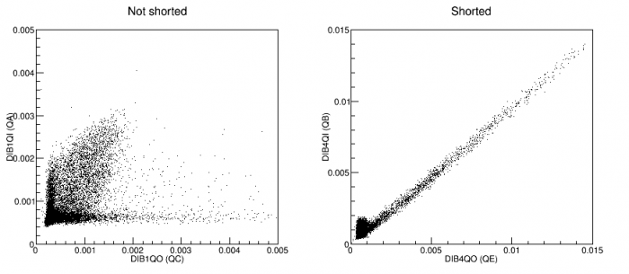
| 1758 | Start 30-minute data series of contact-free/readout=5V/0V data with DIB1/3/4 = DCRC 1/none/2 = master/none/slave, 1000 beginning randoms, and a 30ADC bin threshold trigger on DCRC1 q[1] = qC |
| 1812 | Data looks good in BatViewer so far. |
| 1838 | Start 30-minute data series of contact-free/readout=5V/0V data with DIB1/3/4 = DCRC 1/none/2 = master/none/slave, 1000 beginning randoms, and a 40ADC bin threshold trigger on DCRC2 q[1] = qE |
| 1910 | I'd like to bake without having to mess with the (finally working) DCRC setup. Turn on both DCRC2 LEDs with 0.6 mA current. These are the LEDs on DIB4. |
| 1912 | Tower temp stabilizes at ~500 mK. Let this bake overnight |