2016/12/08 (Thursday)
| Setup: DIB1/3/4 → 3.2 MHz filters → cables 1,2,3 → HV board inputs 1,3,2 → HV board outputs 1,2 → DCRC55(1)/50(3) | |
| Taking overnight data at HV=15 V. between 30 and 40 minutes into the first series (1207_1550), DCRC3pC railed. By the beginning of the second series (1207_1650), DCRC1pB, DCRC1pC, DCRC3pC were all railed. |
|
| 0820 | Main bath = 73.6% |
| 0820 | HV = 15V, Vtest = 0.7 mV. So Vdetector = 14.7 V |
| 0841 | Fill LN2 cold trap full. |
| 1020 | Finish microIbIs at 15 V. For some reason the Vbias values are all lower, significantly, than at 0V. Why is this?? Yesterday I showed that at 30V they were all higher which makes sense, additional parasitic power. The reductions range from 50 to 130 mV at x2 driver gain. The average is 85 mV. |
| 1040 | Finish a semi-full IbIs on DCRCpC to compare with the 0V IbIs curve. The transition region is definitely lower. |
| 1046 | Lower bias to 0V. |
| 1104 | Finish micoIbIs at 0V. The Vbias values are still lower than previous OV values and are even lower than the 15V values taken above. The reductions (from Dec 6th 0V values) range from 60 to 165 mV at 2x driver gain. The average is 112 mV. |
| 1105 | Flash detector for 30s. |
| 1146 | Finish microIbIs at 0V post-flash. Values seem similar to the 15V measurement taken earlier today with a reduction range of 40 to 131 mV at 2x driver gain, with an average of 84mV. |
| 1358 | Tower/MC/Coldplate = 32.9/35.8/226 mK, Still = 1.2 K / 110 μbar, G1/G2 = 187/160 mbar, 1K Pot = 1.69 K / 26 mbar. MB = 65.3%. Boil off rate: a bit faster than slow mode. |
| Begin testing higher Tower temperature to see how oscillation region changes. | |
| 1415 | Apply 5 uW to MC heater. After 5 minutes Tower is around 45 mK, not entirely stable |
| 1420 | Apply 10 uW to MC heater. After 5 minutes Tower levels out around 60 mK, with some wiggles. |
| 1425 | Apply 12 uW to MC heater. Pulses still seen in most channels but getting weaker, probably shouldn't go much higher. After 10 minutes Tower is around 59 mK. |
| 1435 | Apply 14 uW to MC heater. After about 5 minutes Tower is around 62 mK |
| 1440 | Apply 16 uW to MC. After about 5 minutes Tower is around 67 mK. We'll try it here. |
| 1505 | Finish IbIs curve for DCRC1PA. Transition region was small, did not see 10kHz. Tower temp was pretty stable between 66.5 and 67.2 mK. |
| 1600 | Filled in a few IbIs points on DRC1pA |
| 1615 | Finished IbIs and oscillation measurement for DCRC1pB. Although noise at 10kHz went up a bit there was never any sign of a peak at 10kHz, more just a rising of the flat part of the PSD. |
| 1625 | Finish IbIs/oscillation measurement for DCRC1pC, Tower = 66 mK. Again no real sign of 10kHz peak |
| 1635 | Finish IbIs/oscillation measurement for DCRC1pD. Tower = 65.8 mK. In this case there was a shallow peak at 10kHz somewhere in the transition region. |
| 1640 | Turn off MC heater to let Tower cool to base |
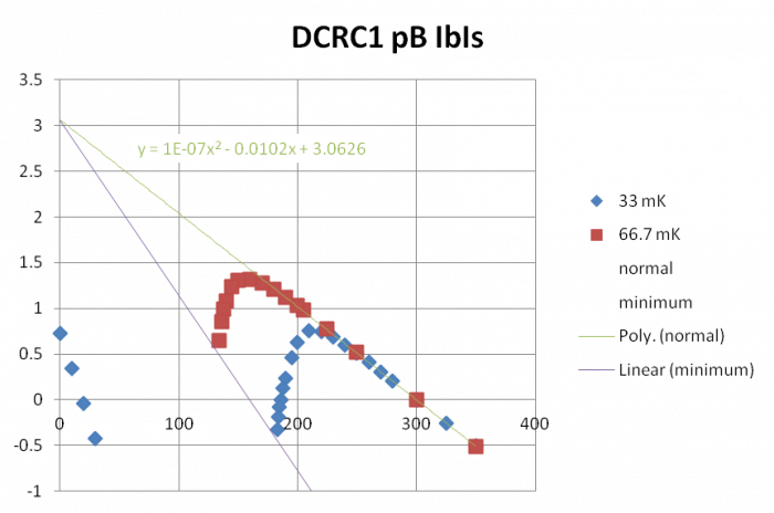
The plot above shows the IbIs results for one channel at the two temperatures. The results fit theoretical expectations. Shown here is a quadratic extrapolation of the normal part of the curve back to the vertical axis to find the voltage offset for the normal and transition part of the curve. The four points near the vertical axis represent the superconducting part of the curve. The transition part of the curve should extend from the normal down to a line that has exactly 1/2 the slope of the superconducting part. The data points taken in transition end at the lowest bias before the channel falls into superconducting.
| 1700 | Tower = 35 mK |
|---|---|
| 1700 | Flash detector. (Note that HV is at 0V) |
| 1705 | Prebias detector to 55 V |
| 1710 | Dial HV back down to 45 V |
| 1720 | Tower = 34.5 mK and falling. Return all channels to standard QET biases and adjust driver offsets. Set Driver Gains to 4x. |
| 1725 | HV = 45 V, Vtest = 2.5 mV. So Vdetector = 43.9 V |
| 1732 | Start a sequence of 14 1-hour series of 45V data with Frontend Gain = 5, OG = 4, DCRC3pB intentionally railed, with 1000 beginning randoms, with no flashing in between series, and a 35ADC bin threshold trigger on DCRC3 pD. |
| 1810 | Fill LN2 cold trap full. |
| 1905 | DCRC1pC is railed (too low) and threshold seems too high, will try to adjust from home… |
| 1943 | Adjust DCRC1pC ADCoffset from 0.33 to 0.23 |
| 1944 | Adjust DCRC3pD threshold from 35 to 30 |
| 1955 | DCRC1pC still seems railed and threshold still seems high, will try again… |
| 1958 | Adjust DCRC3pD threshold from 30 to 25 |
| 1959 | Adjust DCRC1pC ADCoffset from 0.23 to 0.13 |
| 2005 | Threshold looks ok now but DCRC1pC still railed |
| 2008 | Adjust DCRC1pC ADCoffset from 0.13 to -0.07 |
| 2015 | OK DCRC1pC is unrailed but probably a little too high, baseline around 11000 in the BatViewer window (max is around 17000). Try tweaking it some… |
| 2017 | Adjust DCRC1pC ADCoffset from -0.07 to -0.03 |
| 2025 | DCRC1pC baseline is around 7500 now. Let's try to get it close to 2500. |
| 2028 | Adjust DCRC1pC ADCoffset from -0.03 to 0.0 |
| 2028 | Adjust DCRC1pC ADCoffset from 0.0 to 0.03 |