Table of Contents
2013/05/13
Update on Stripline Work
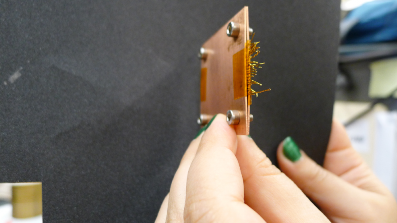
| Figure 1: Twenty-five twisted pairs of 30 AWG Cu-Be wire sandwiched between heat sinks. |
|---|
 |
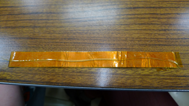
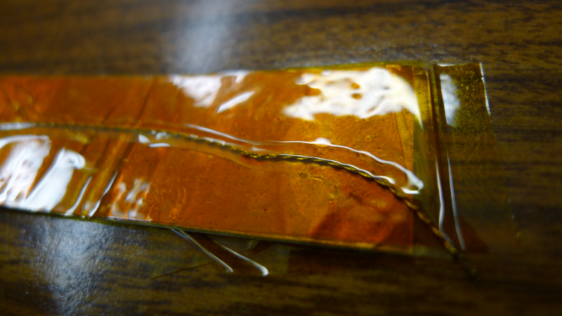
| Figure 2: Kapton tape sandwiching 30 AWG Cu-Be twisted pair. |
|---|
 |
 |
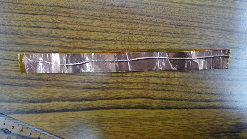
| Figure 3: Copper and kapton tapes sandwiching 30 AWG Cu-Be twisted pair. |
|---|
 |
Replacement of He-3 Pump's Shaft Seals
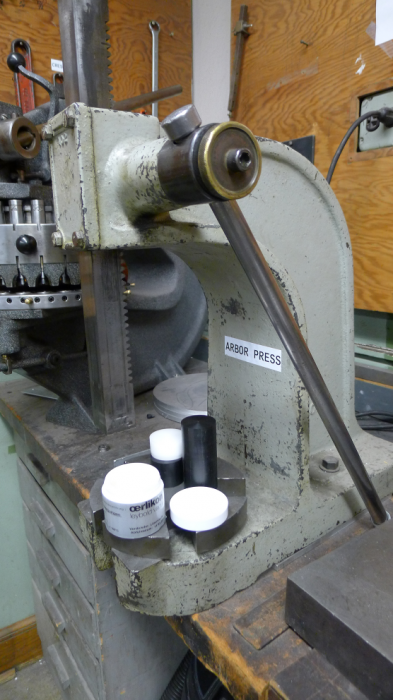
| Figure 4: Plastic cylinders and arbor press. |
|---|
 |
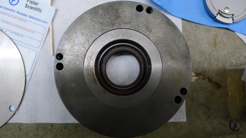
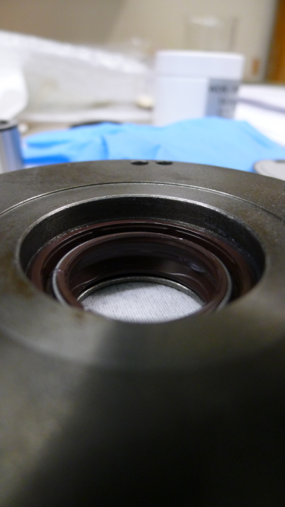
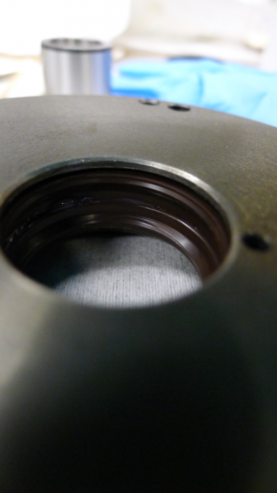
| Figure 5: Shaft seals in centering disc. | |
|---|---|
 |
|
 |  |
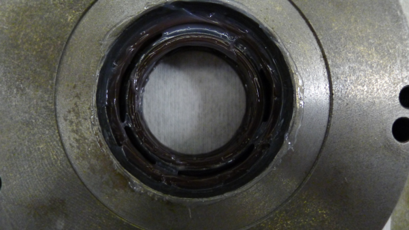
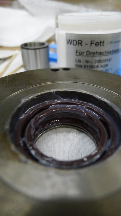
| Figure 6: Shaft seals in centering disc coated in vacuum grease. | |
|---|---|
 |  |
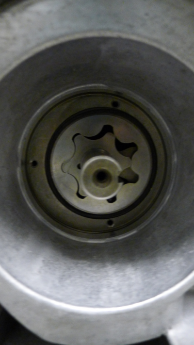
| Figure 7: Large O-ring mounted in groove on end plate. |
|---|
 |
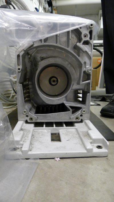
| Figure 8: Centering disc with shaft seals and holding panel fastened to end plate. |
|---|
 |
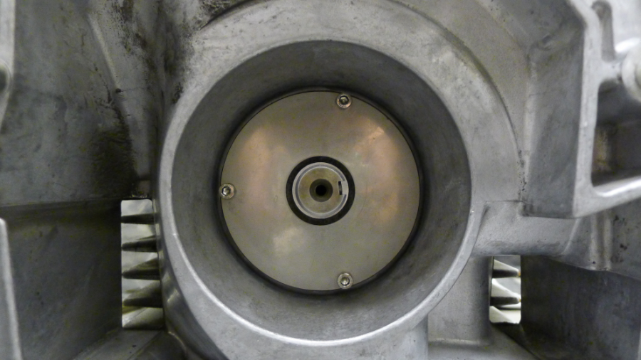
| Figure 9: Bushing inserted over shaft and through middle of shaft seals in centering disc. |
|---|
 |
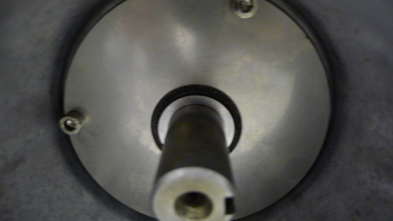 |
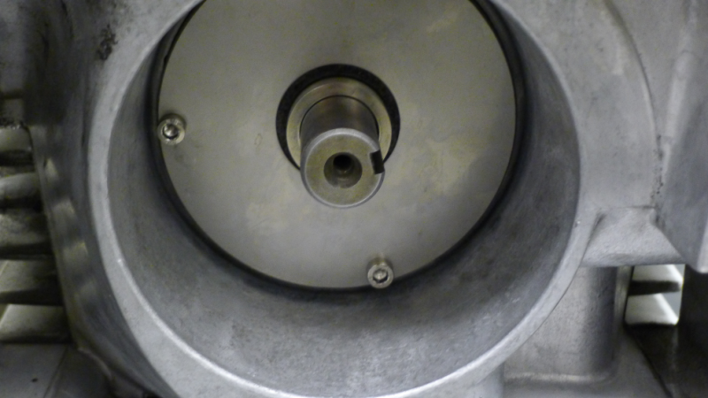
| Figure 10: Compression ring and small O-ring mounted. |
|---|
 |
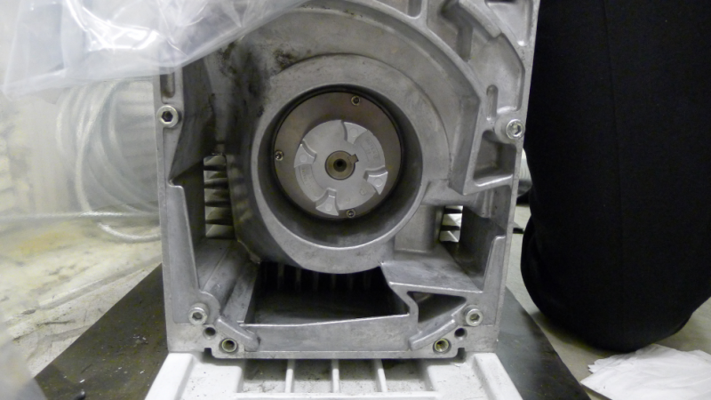
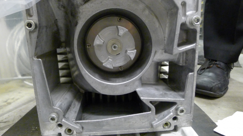
| Figure 11: Pump-half of coupling element mounted. |
|---|
 |
| Figure 12: Spring washer and screw mounted. |
|---|
 |
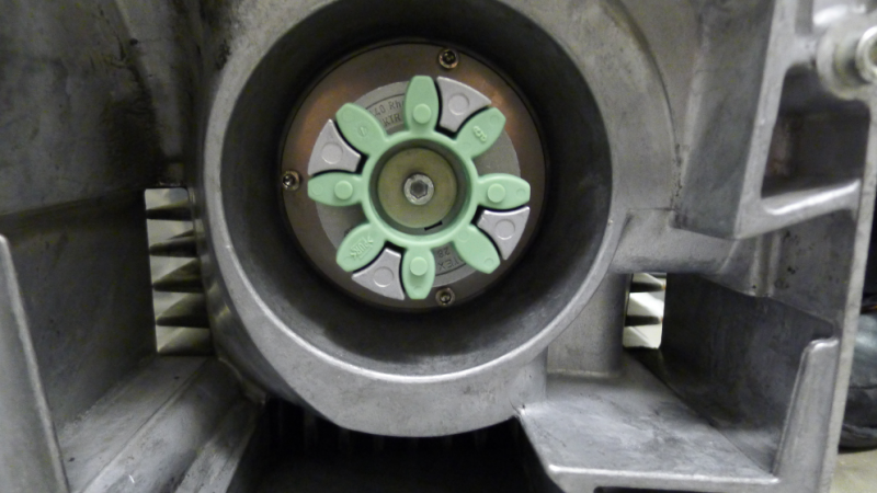
| Figure 13: Coupling element mounted. |
|---|
 |