Table of Contents
2013/05/04
Both striplines 21 & 27 have been plagued by severed traces. As demonstrated with stripline 21, The situation is likely to become worse during cooldown as the traces contract. Thus partially severed traces may move away from each other at the point of fracture and fail continuity checks. As no more striplines are available to replace these two, two courses of action are discussed below.
Combining Striplines 21 & 27
Although both striplines have suffered fractures, there should be enough traces between them to read out one DIB. Therefore, one can combine both striplines, using interface boards at the warm and cold ends to divert signals up good traces and then restore their paths before they hit the DCRC.
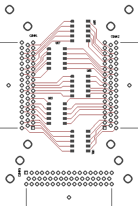
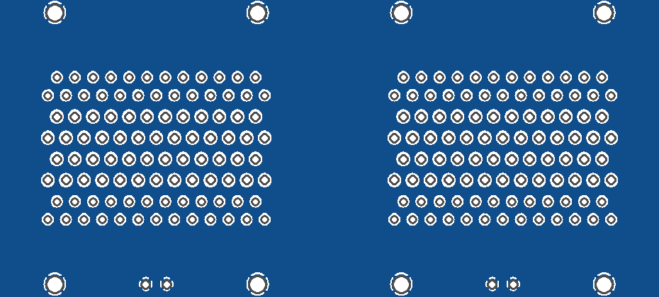
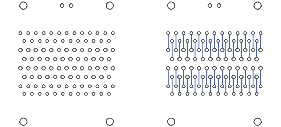
The warm end PCB is shown in Fig. 1 and will sit within the ebox. Looking at the component side, the D-sub 50 connector on the left will plug into the ebox. The D-sub 50 connector on the right will mate with stripline 27. Stripline 21 will connect with the D-sub 50 connector at the bottom. Switches are present to ensure that a broken trace doesn't reconnect and thus complicate the circuit.
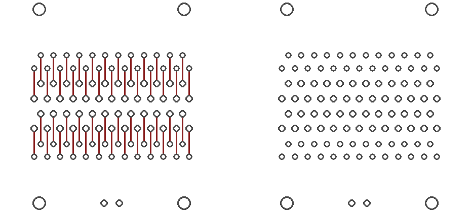
The cold end PCB is shown in Fig. 2. Looking at the component side, the right side of the board will plug into the SQUET card, which will feature MillMax receptacles. Stripline 27 will then plug into the same side of the PCB. Stripline 21 will connect with MillMax pins on the left side of the PCB.
When a trace on stripline 27 fails, a suitable trace on stripline 21 will be sought and a wire will be soldered between the corresponding pins on the cold end to ensure good contact at liquid helium temperatures. At the warm end, the switch that connects the severed trace to the DCRC will be opened and 30 AWG wire shall be wrapped around corresponding pins on stripline 21 and the DCRC connectors.
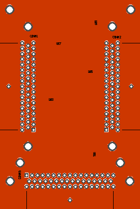
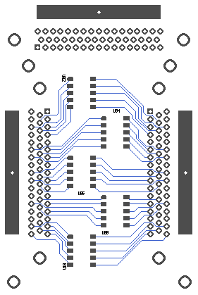
| Figure 1: Stripline Switch Warm End PCB: component side (left); ground plane (centre); and solder side (right). | ||
|---|---|---|
 |  |  |
| Figure 2: Stripline Switch Cold End PCB (Scale 3:1). |
|---|
| Component Side. |
 |
| Ground Plane. |
 |
| Solder Side. |
 |
MIT's Stripline
MIT have 250 ft of manganin and 400 ft of Cu-Be wire spare. As the striplines are 10 ft long, we will only have enough manganin wire for 25 traces. As MIT's design requires 38 manganin wires, some wires cannot be commissioned. The following can potentially be disposed of (in order of priority):
- 1 x Tsense+ : we never use the FET temperature sensor.
- 13 x QET Return lines : we have a total of 17 QET Return lines, but only one per channel is required, so up to 13 can be dropped.
- 2 x LED : we could use LEDs on the other DIBs to flash the detector.
Removing the temperature sensor and 13 QET Return lines would reduce the number of required wires to 24. If we encountered a severed wire at a future date, we could simply use one of the LED lines to replace it, sacrificing the ability to flash the detector from that DIB.
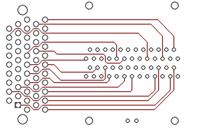
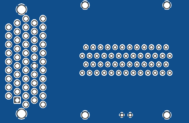
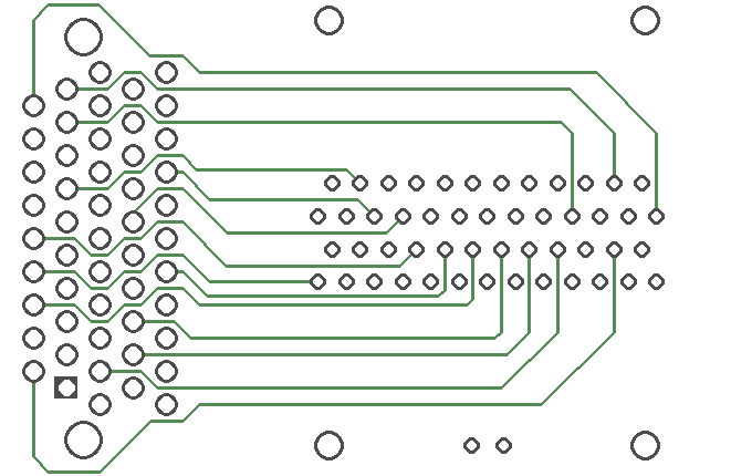
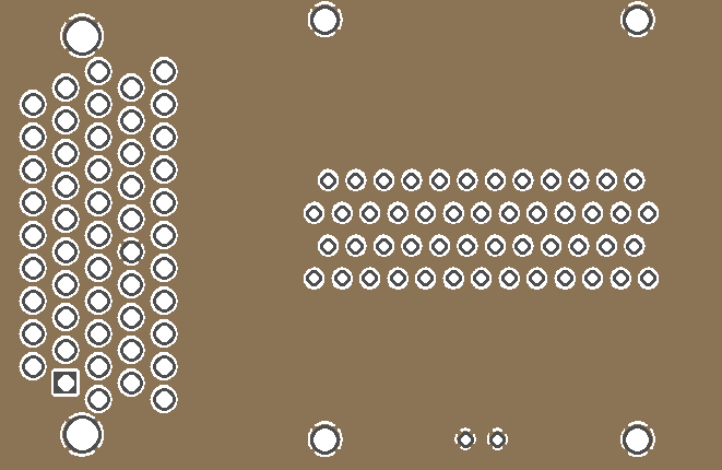
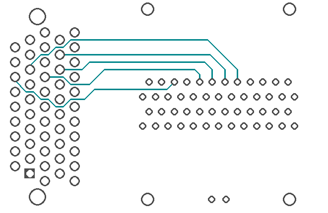
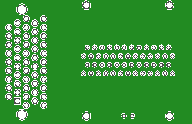
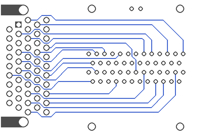
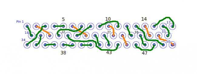
The cold end PCB is illustrated in Fig. 3 and proposed pinouts are given in Table 1. The cables shall be connected to a D-sub 50 connector within the ebox at the warm end. At the cold end, a micro D-sub 51-pin connector shall be used to plug the cable into the PCB. It was decided to use 51-pin connectors and connect all SQUET card pins on the PCB to leave the option open to upgrade the cable from 37 to 51 wires. As we have an extra pin to play with, ground shall be delivered through micro D-sub connector pin 42.
| Figure 3: MIT Cable Cold End PCB (Scale 3:1). |
|---|
| Component Side. |
 |
| Ground Plane 1. |
 |
| Signal Plane 1. |
 |
| Ground Plane 2. |
 |
| Signal Plane 2. |
 |
| Ground Plane 3. |
 |
| Solder Side. |
 |
| Table 1: Pinouts for MIT Cable. | ||||||
|---|---|---|---|---|---|---|
| Signal | Bulkhead D pin | Stripline D socket | Material | Wire Pair | Micro D pin | FET Card Pin |
| QET A return | 1 | 17 | manganin | 1 | 1 | 2 |
| Feedback B | 2 | 16 | manganin | 2 | 36 | 14 |
| QET A | 3 | 15 | manganin | 1 | 2 | 15 |
| SQUID bias A | 4 | 14 | Cu-Be | 3 | 37 | 16 |
| QET C return | 5 | 13 | manganin | 19 | 4 | 4 |
| Feedback D return | 6 | 12 | manganin | 5 | 3 | 5 |
| QET C | 7 | 11 | manganin | 4 | 22 | 18 |
| SQUID bias C | 8 | 10 | Cu-Be | 6 | 24 | 19 |
| QET C return | 9 | 9 | manganin | 4 | 38 | 7 |
| QET C return | 10 | 8 | manganin | 20 | 5 | 8 |
| Qo bias | 11 | 7 | manganin | 16 | 40 | 21 |
| Qo drain | 12 | 6 | Cu-Be | 7 | 27 | 22 |
| QET A return | 13 | 5 | manganin | 21 | 25 | 10 |
| QET A return | 14 | 4 | manganin | 21 | 26 | 11 |
| Qi bias | 15 | 3 | manganin | 17 | 44 | 24 |
| Qi drain | 16 | 2 | Cu-Be | 8 | 47 | 25 |
| QET A return | 17 | 1 | manganin | 22 | 8 | 13 |
| Feedback B return | 18 | 33 | manganin | 2 | 19 | 1 |
| SQUID bias B | 19 | 32 | Cu-Be | 9 | 35 | 27 |
| SQUID A return | 20 | 31 | Cu-Be | 3 | 20 | 3 |
| Feedback A return | 21 | 30 | manganin | 10 | 33 | 41 |
| Feedback D | 22 | 29 | manganin | 5 | 21 | 17 |
| SQUID bias D | 23 | 28 | Cu-Be | 11 | 15 | 30 |
| SQUID C return | 24 | 27 | Cu-Be | 6 | 23 | 6 |
| Feedback C return | 25 | 26 | manganin | 12 | 32 | 44 |
| LED 2 | 26 | 25 | manganin | 18 | 6 | 20 |
| Qo source | 27 | 24 | Cu-Be | 7 | 28 | 33 |
| QET C return | 28 | 23 | manganin | 20 | 9 | 9 |
| QET B return | 29 | 22 | manganin | 13 | 49 | 47 |
| Qo feedback | 30 | 21 | manganin | 16 | 41 | 23 |
| Qi source | 31 | 20 | Cu-Be | 8 | 48 | 36 |
| QET A return | 32 | 19 | manganin | 23 | 7 | 12 |
| QET B return | 33 | 18 | manganin | 22 | 11 | 50 |
| SQUID B return | 34 | 50 | Cu-Be | 9 | 51 | 39 |
| QET B | 35 | 49 | manganin | 19 | 17 | 26 |
| QET D return | 36 | 48 | manganin | 14 | 18 | 40 |
| Feedback A | 37 | 47 | manganin | 10 | 34 | 28 |
| QET D | 38 | 46 | manganin | 14 | 16 | 29 |
| SQUID D return | 39 | 45 | Cu-Be | 11 | 50 | 42 |
| QET D return | 40 | 44 | manganin | 13 | 14 | 43 |
| Feedback C | 41 | 43 | manganin | 12 | 31 | 31 |
| LED 1 | 42 | 42 | manganin | 18 | 39 | 32 |
| QET D return | 43 | 41 | manganin | 24 | 30 | 45 |
| QET D return | 44 | 40 | manganin | 24 | 29 | 46 |
| FET heater + | 45 | 39 | manganin | 15 | 46 | 34 |
| FET heater - | 46 | 38 | manganin | 15 | 45 | 35 |
| QET B return | 47 | 37 | manganin | 25 | 13 | 48 |
| QET B return | 48 | 36 | manganin | 25 | 12 | 49 |
| FET Tsense + | 49 | 35 | manganin | 23 | 10 | 37 |
| Qi feedback | 50 | 34 | manganin | 17 | 43 | 38 |
| Ground | Cu-Be | 42 | ||||
Stripline Cable Heat-sinking Calculations
This section will cover the heat load calculations used to determine the heat sink temperatures of the cable to be connecting 300K to the 4.2 K SQUET card. These calculations will be based off of the work in Appendix A of Procurement Specification for CDMS Test Facility 300-4K Cable by A. Anderson, J. Billard, and E. Figueroa-Feliciano. The cable to be used in K100 will differ from this cable as it will not have a jumper cable connected to the 300-4K cable but will instead directly connect to the SQUET cards. There will also be two heat sinks attached to the cable at 32“ and 18” from the SQUET. The total heat load equation will thus be given by,
 ,
where  ,
 ,
 ,
 are the heat loads from room temperature, the heat sinks, and the SQUET card respectively. These calculations will follow model 1 from Appendix A, and thus treat all wires within the cable as one wire (per each material Cu/Be and Mn) with a cross section equal to the sum of each wires cross section. With this model, the heat load from 300K will be,

where S is the cross section of the wire. The 12 Cu/Be wires are #32 AWG and the 38 Mn wires are #38 AWG. L is the length of the wire from 300K to the first heat sink (the cable is 3m long and the first heat sink is 32“ from the SQUET). κ is the thermal conductivity integral of the given material. The conductivity integral for Mn is given in appendix A. The thermal conductivity for Beryllium Copper can be found here. T gives the temperature at the designated heat sink.
Similarly, the heat load through the SQUET card will be,

where l is the 18” from the SQUET card to the second heat sink. The heat sinks connect the wire to 4.2K through 2cm by 5cm copper plates in direct contact with the 0.0035“ thick Kapton tape. The thermal conductivity of Kapton tape at 0-5K is given here. Thus the heat load across each heat sink is,
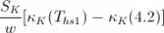 and
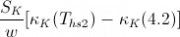
where w is the thickness of the Kapton tape. Plugging these into the total heat load expression results in an equation with two unknowns; both heat sink temperatures cannot be solved for simultaneously. Thus, an approximate value for the first heat sink is found by initially neglecting the heat sink nearest to the SQUET card. This gives a temperature value for the first heat sink of 4.205K. When this value is plugged back into the full heat load expression with the second heat sink included, the temperature of the second heat sink is found to be 4.2000K. These calculations were found using NSolve in Mathematica, with work shown here.