2013/03/07
| 1115 | N2 cold trap emptied and ice from bottom removed. Stop pumping on fridge lines and isolate them, place nitrogen cold traps back in their bath and start cryocleaning mixture through nitrogen cold trap 2. Dump pressure 784 mbar, so mixture is rather dirty. |
|---|---|
| 1210 | Conducted continuity check of stripline 20. Trace 10 (Qo bias, FET card pin 21) is the only severed one. It is possible that the next traces to fail will be 8 (Qo drain, FET card pin 22), 9 (QET C Return, FET card pin 9), 11 (QET C Return, FET card pin 8) & 12 (LED 2, FET card pin 20). However, we have removed and replugged the SQUET card, and adjusted the position of this stripline at least a couple of times without any ill effect on the surrounding traces. We did check that the socket itself was not a problem by checking the solder joints on the back of the stripline. However, this confirmed that the trace was indeed severed, exonerating the socket. If this remains stable and we only lose Qo bias, we can recover this stripline using an interface board in a future run. It would be useful to conduct a thermal cycle before arriving at a decision. |
| 1230 | We have three possibilities (copied from email to Vuk): |
- We use stripline 21 (the really broken one) and don't do anything. Although QET D is severed, QET D Return isn't, and if the purpose of this connection is to simply ground the grounded electrode, this should be fine. However, there is probably some reason why this wouldn't work.
- We use stripline 21 (the really broken one) and short Pins 29 (QET D) to 18 (QET C). The failure probability for QET C is pretty large. Alternatively or additionally we could short Pins 46 (QET D Return) to 13 (QET A Return), whose trace is closer to the edge of the stripline.
- We use stripline 20 (Qo bias severed) and short Pins 21 (Qo bias) to 24 (Qi bias). This means by setting Qi's bias we also set Qo's. If we do not see any other severed traces on this stripline, this would be my preferred option. However, I do not know if I have considered the circuit carefully enough.
| Vuk replied that option 3 may (unsure) compromise ionisation signals by changing cross-talk. Option 3 also would not allow us to run Qi & Qo at different biases if we determined this to be desirable. Option 2 is safer and connecting QET D Return to QET A Return would be a good idea. Finally, Vuk felt that sandwiching stripline 21 between 2 copper sheets is unlikely to work as the two ends of the break may move away from each other due to thermal contraction as we cool. | |
| Let's use stripline 21 and attempt to short the following with a wire-wrap borrowed from Al: |
| Table 1: Proposed shorting scheme for stripline 21. | |||||||
|---|---|---|---|---|---|---|---|
| From | To | ||||||
| Signal | FET card pin | Trace | Condition | Signal | FET card pin | Trace | Condition |
| QET D | 29 | 32 | severed | QET C | 18 | 16 | in danger |
| QET D Return | 40 | 29 | severed | QET A Return | 10 | 7 | safe |
| QET D Return | 43 | 35 | severed | QET A Return | 11 | 5 | safe |
| QET D Return | 45 | 39 | in danger | QET A Return | 12 | 3 | safe |
| QET D Return | 46 | 41 | in danger | QET A Return | 13 | 1 | safe |
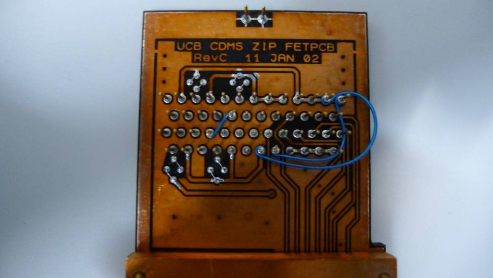
| 1655 | Found spool of good quality 30 AWG wire from 1976 lying in the laboratory! Short QET D to QET C, and QET D Return pins 45 & 46 to QET A Return pins 12 & 13 respectively using wire: |
|---|
| Figure 1: Connector on SQUET card ZC-70 displaying shorted connections. |
|---|
 |
| 1750 | Conduct electrical check at room temperature before sealing flange. For the purposes of this run, everything looks good. On DIB 1, Qi & Qo biases to QET C Returns conduct through QET C/QET D short. Isolation checks for DIB 1 show that wire insulation is intact - shall continue to monitor this during cooldown. |
|---|
| Table 2: Room temperature electrical check for G101b DIB 1. | |||||
|---|---|---|---|---|---|
| Detector: | G101b DIB1 | BH: | Stripline: | 21 | |
| SC: | ZB1-1-6 | 300 K | |||
| Face: | 2 | Date | 2012-03-07 | ||
| SQUET: | ZC70 | Who | HC | ||
| Signal | Pos. lead | Gnd lead | Nominal | Actual | Chassis |
| (Gnd lead) | |||||
| Nominal: | |||||
| < 0.1 nS | |||||
| SQUID bias A/Ret | 4 | 20 | 3 - 5 k | open | OK |
| SQUID bias B/Ret | 19 | 34 | 4.4k | OK | |
| SQUID bias C/Ret | 8 | 24 | 4.7k | OK | |
| SQUID bias D/Ret | 23 | 39 | 5.2k | OK | |
| Feedback A/Ret | 37 | 21 | 15 - 25 k | 29k | OK |
| Feedback B/Ret | 2 | 18 | 25k | OK | |
| Feedback C/Ret | 41 | 25 | 28k | OK | |
| Feedback D/Ret | 22 | 6 | 35k | OK | |
| QET A/Ret | 3 | 1, 13, 14, 17, 32 | 60 - 80 | 166,151,145,149,147 | OK |
| QET B/Ret | 35 | 29, 33, 47, 48 | 84,83,97,83 | OK | |
| QET C/Ret | 7 | 5, 9, 10, 28 | 157,85,76,85 | OK | |
| QET D/Ret | 38 | 36, 40, 43, 44 | 93,90,89,90 | OK | |
| QET C/QET A Ret | 7 | 1, 13, 14, 17, 32 | 110,93,88,91,89 | ||
| QET C/QET D Ret | 7 | 36, 40, 43, 44 | 90,87,86,87 | ||
| FET heater +/- | 45 | 46 | 1.0 - 1.1 k | 1.07k | OK |
| Qi bias/QET Ret | 15 | 24 - 26 nS | open (B); 26 (A,C,D) | OK | |
| Qo bias/QET Ret | 11 | open (B); 26 (A,C,D) | OK | ||
| Qi feedback/Drain/Source | 50 | 16, 31 | 15 - 17 nS | 23,23 | OK |
| Qo feedback/Drain/Source | 30 | 12, 27 | 23,23 | OK | |
| Qi drain | 16 | chassis | < 0.1 nS | – | OK |
| Qo drain | 12 | chassis | – | OK | |
| Qi source | 31 | chassis | – | OK | |
| Qo source | 27 | chassis | – | OK | |
| FET Tsense +/FET heater- | 49 | 46 | 0.6 - 0.7 V | 0.715 | OK |
| LED 1 | 42 | chassis | 1.0 - 1.1 V | 1.135 | – |
| LED 2 | 26 | chassis | open | – | |
| Isolation Checks | |||||
| QET C/Feedback D | 18 | 17 | <0.1 nS | OK | – |
| QET C/SQUID bias D | 18 | 30 | OK | – | |
| QET D/Feedback D | 29 | 17 | OK | – | |
| QET D/SQUID bias D | 29 | 30 | OK | – | |
| QET A Ret/QET B Ret | 1, 13, 14, 17, 32 | 29, 33, 47, 48 | OK | – | |
| QET A Ret/Qi feedback | 1, 13, 14, 17, 32 | 38 | OK | – | |
| QET A Ret/Qi drain | 1, 13, 14, 17, 32 | 25 | OK | – | |
| QET D Ret/QET B Ret | 36, 40, 43, 44 | 29, 33, 47, 48 | OK | – | |
| QET D Ret/Qi feedback | 36, 40, 43, 44 | 38 | OK | – | |
| QET D Ret/Qi drain | 36, 40, 43, 44 | 25 | OK | – | |
| Table 3: Room temperature electrical check for G101b DIB 2. | |||||
|---|---|---|---|---|---|
| Detector: | G101b DIB2 | BH: | Stripline: | 19 | |
| SC: | ZB1-1-9 | 300 K | |||
| Face: | 5 | Date | 2013-03-07 | ||
| SQUET: | ZC23 | Who | HC | ||
| Signal | Pos. lead | Gnd lead | Nominal | Actual | Chassis |
| (Gnd lead) | |||||
| Nominal: | |||||
| < 0.1 nS | |||||
| SQUID bias A/Ret | 4 | 20 | 3 - 5 k | 4.4k | OK |
| SQUID bias B/Ret | 19 | 34 | 5.0k | OK | |
| SQUID bias C/Ret | 8 | 24 | 4.6k | OK | |
| SQUID bias D/Ret | 23 | 39 | 4.3k | OK | |
| Feedback A/Ret | 37 | 21 | 15 - 25 k | 18k | OK |
| Feedback B/Ret | 2 | 18 | 20k | OK | |
| Feedback C/Ret | 41 | 25 | 19k | OK | |
| Feedback D/Ret | 22 | 6 | 18k | OK | |
| QET A/Ret | 3 | 1, 13, 14, 17, 32 | 60 - 80 | 90,91,85,89,86 | OK |
| QET B/Ret | 35 | 29, 33, 47, 48 | 87,86,100,86 | OK | |
| QET C/Ret | 7 | 5, 9, 10, 28 | 85,85,75,85 | OK | |
| QET D/Ret | 38 | 36, 40, 43, 44 | 86,84,84,84 | OK | |
| FET heater +/- | 45 | 46 | 1.0 - 1.1 k | 1.07k | OK |
| Qi bias/QET Ret | 15 | 24 - 26 nS | open (A,B,C); 26 (D) | OK | |
| Qo bias/QET Ret | 11 | open (A,B,C); 25 (D) | OK | ||
| Qi feedback/Drain/Source | 50 | 16, 31 | 15 - 17 nS | 23,23 | OK |
| Qo feedback/Drain/Source | 30 | 12, 27 | 23,23 | OK | |
| Qi drain | 16 | chassis | < 0.1 nS | – | OK |
| Qo drain | 12 | chassis | – | OK | |
| Qi source | 31 | chassis | – | OK | |
| Qo source | 27 | chassis | – | OK | |
| FET Tsense +/FET heater- | 49 | 46 | 0.6 - 0.7 V | 0.725 | OK |
| LED 1 | 42 | chassis | 1.0 - 1.1 V | 1.137 | – |
| LED 2 | 26 | chassis | 1.13 | – | |
| 1827 | Fed Cricket 4 pellets. |
|---|---|
| 2100 | IVC sealed. Start evacuating IVC. |
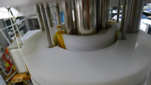
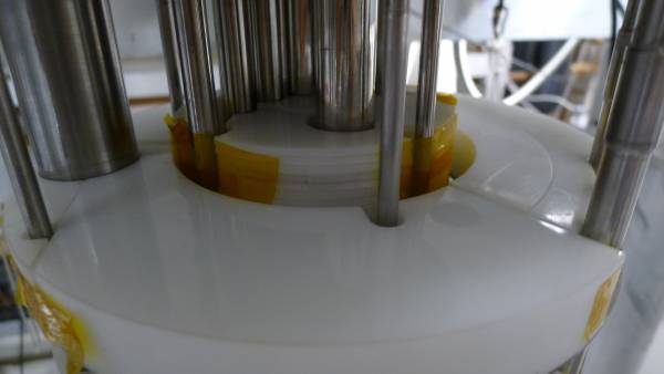
| 2200 | Installed polyethylene shield within baffles above IVC. |
| Figure 2: Photographs of polyethylene shield within baffles above IVC. | |
|---|---|
 |  |
| 2240 | Pump mixture into dump in preparation for cleaning cold traps. |
|---|---|
| 2330 | Open gate valve, condenser line speedivalve and valve V1 on IGH to evacuate mixing chamber lines in fridge. |