2012/06/29
| 0020 | Conduct tower level continuity check. Found short to ground. Take side coaxes off one-by-one and try to isolate short. |
|---|---|
| 0230 | Found source of short: pins 7 & 8 on new SCUHBA extender plug PCB are shorted. Tried to look for visible signs of short, but could not find any. Additionally, ran soldering iron across mask in attempt to remove solder: did not work… well partly worked as resistance is now 15 MΩ rather than 0.2 Ω. Finally, tried to scrap solder off with scalpel: no luck. Will discuss with others present for possible solution. |
| 0425 | Had a brief discussion. Looked under microscope, but nothing seemed untoward. Conducted another electrical check, and found that board is acting as a capacitor. All pins seem to be shorted, but resistance keeps rising. Did not notice this increase before. Looks like running the soldering iron over the mask did the trick. |
| Adapter plate requires some work. We do not have the necessary tools to do this easily. Will have to wait for mechanical workshop to open in the morning. Therefore, stop all work. Go home, get some sleep. It's going to be a busy day. Leave tower in clean room. Finish assembly and electrical checks in the morning. | |
| Fill N2 cold trap full. | |
| 1130 | Stop pumping on dewar. |
| 1240 | Fill N2 cold trap full. |
| 1300 | Pump mixture into dump in preparation for cleaning cold traps. |
| 1330 | Start cleaning nitrogen and helium cold traps. |
| Resume tower assembly procedure. | |
| 1440 | Conduct tower level continuity checks: |
| Detector | G103a | DIB | 1 | |
|---|---|---|---|---|
| side coax | ZB1-1-6 | date/who: | 2012-06-29 | HC & AK |
| face | 2 | |||
| +lead | - lead | signal | typical | measured |
| 1 | 2 | QET A | 100 to 200 Ω | 211 Ω |
| 2 | 4 | QETA-B | 100 to 200 Ω | 235 Ω |
| 3 | 4 | QET B | 100 to 200 Ω | 219 Ω |
| 4 | 6 | QETB-C | 100 to 200 Ω | 216 Ω |
| 5 | 6 | QET C | 100 to 200 Ω | 188 Ω |
| 6 | 8 | QETC-D | 100 to 200 Ω | 204 Ω |
| 7 | 8 | QET D | 100 to 200 Ω | 152 Ω |
| 2 | 8 | QETA-D | 100 to 200 Ω | 210 Ω |
| chassis | 10 | LED2 Rforward | 8 to 9 MΩ | 755 kΩ |
| chassis | 10 | LED2 Vforward | 1.0 to 1.1 V | 1.088 V |
| 10 | chassis | LED2 Rreverse | <1 nS | <0.8 nS |
| 1 | 11 | Qo Rbias | 24 to 26 nS | 26 nS |
| 12 | 11 | Qo C coupling | <1 nS | <0.4 nS |
| 12 | 13 | Qo Rfeedback | 24 to 26 nS | 26 nS |
| 1 | 14 | Qi Rbias | 24 to 26 nS | 26 nS |
| 15 | 14 | Qi C coupling | <1 nS | <0.4 nS |
| 15 | 16 | Qi Rfeedback | 24 to 26 nS | 26 nS |
| Detector | G103a | DIB | 2 | |
|---|---|---|---|---|
| side coax | ZB1-1-9 | date/who: | 2012-06-29 | HC & AK |
| face | 5 | |||
| +lead | - lead | signal | typical | measured |
| 1 | 2 | QET A | 100 to 200 Ω | 201 Ω |
| 2 | 4 | QETA-B | 100 to 200 Ω | 182 Ω |
| 3 | 4 | QET B | 100 to 200 Ω | 116 Ω |
| 4 | 6 | QETB-C | 100 to 200 Ω | 183 Ω |
| 5 | 6 | QET C | 100 to 200 Ω | 166 Ω |
| 6 | 8 | QETC-D | 100 to 200 Ω | 169 Ω |
| 7 | 8 | QET D | 100 to 200 Ω | 117 Ω |
| 2 | 8 | QETA-D | 100 to 200 Ω | 192 Ω |
| chassis | 9 | LED1 Rforward | 8 to 9 MΩ | 754 kΩ |
| chassis | 10 | LED2 Rforward | 8 to 9 MΩ | 774 kΩ |
| chassis | 9 | LED1 Vforward | 1.0 to 1.1 V | 1.086 V |
| chassis | 10 | LED2 Vforward | 1.0 to 1.1 V | 1.088 V |
| 9 | chassis | LED1 Rreverse | <1 nS | <2.0 nS |
| 10 | chassis | LED2 Rreverse | <1 nS | <0.9 nS |
| 1 | 11 | Qo Rbias | 24 to 26 nS | 25 nS |
| 12 | 11 | Qo C coupling | <1 nS | <0.3 nS |
| 12 | 13 | Qo Rfeedback | 24 to 26 nS | 26 nS |
| 1 | 14 | Qi Rbias | 24 to 26 nS | 26 nS |
| 15 | 14 | Qi C coupling | <1 nS | <0.3 nS |
| 15 | 16 | Qi Rfeedback | 24 to 26 nS | 26 nS |
| Detector | G103a | DIB | 3 | |
|---|---|---|---|---|
| side coax | ZB1-1-11 | date/who: | 2012-06-29 | HC & AK |
| face | 6 | |||
| +lead | - lead | signal | typical | measured |
| 1 | 2 | QET A | 100 to 200 Ω | 186 Ω |
| 2 | 4 | QETA-B | 100 to 200 Ω | 230 Ω |
| 3 | 4 | QET B | 100 to 200 Ω | 210 Ω |
| 4 | 6 | QETB-C | 100 to 200 Ω | 189 Ω |
| 5 | 6 | QET C | 100 to 200 Ω | 132 Ω |
| 6 | 8 | QETC-D | 100 to 200 Ω | 213 Ω |
| 7 | 8 | QET D | 100 to 200 Ω | 208 Ω |
| 2 | 8 | QETA-D | 100 to 200 Ω | 232 Ω |
| chassis | 9 | LED1 Rforward | 8 to 9 MΩ | 765 kΩ |
| chassis | 9 | LED1 Vforward | 1.0 to 1.1 V | 1.086 V |
| 9 | chassis | LED1 Rreverse | <1 nS | <0.9 nS |
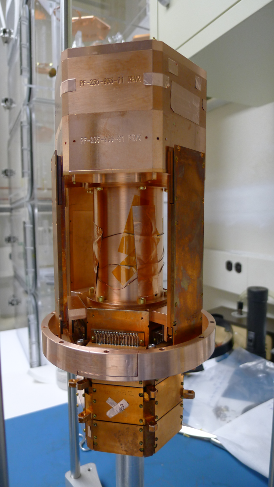
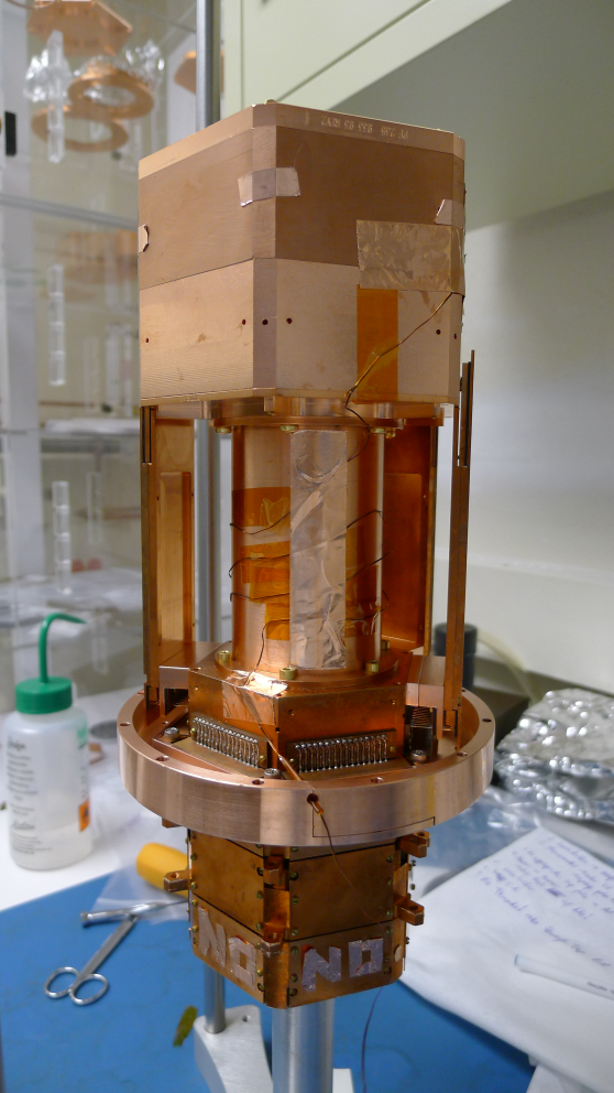
| 1455 | Tower assembly procedure completed. Tower taken to mini-clean room to commence installation. |
|---|
| Figure 1: Assembled tower. | |
|---|---|
 |  |
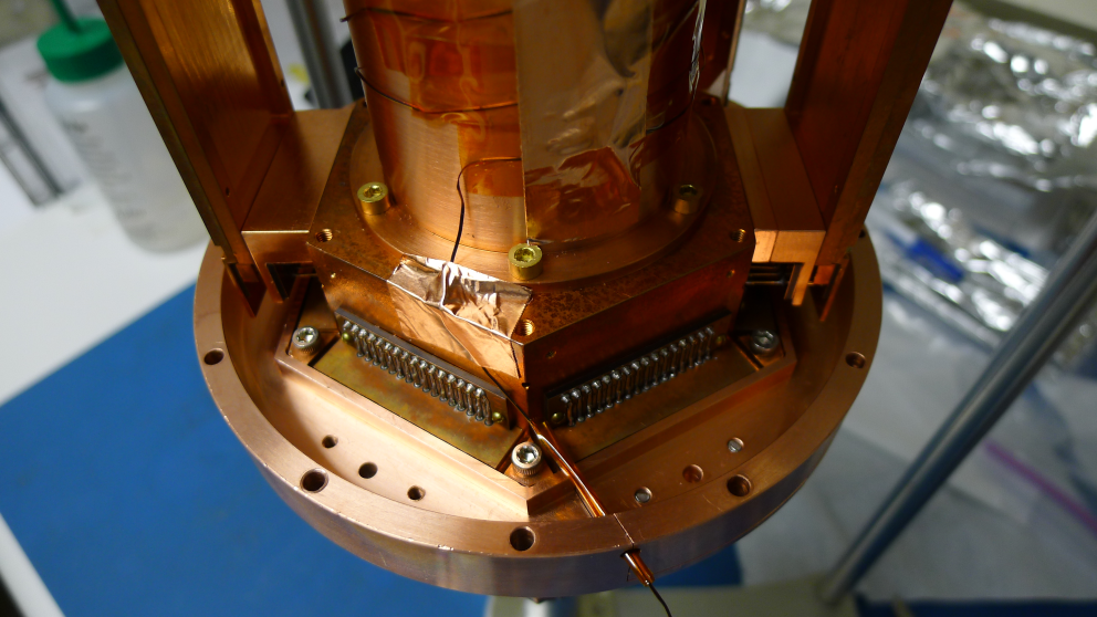
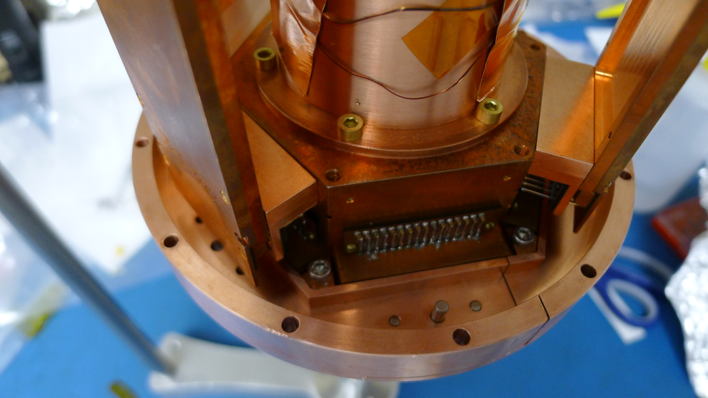
| Figure 2: New adapter plate with space for tower themometer wire. |
|---|
 |
 |
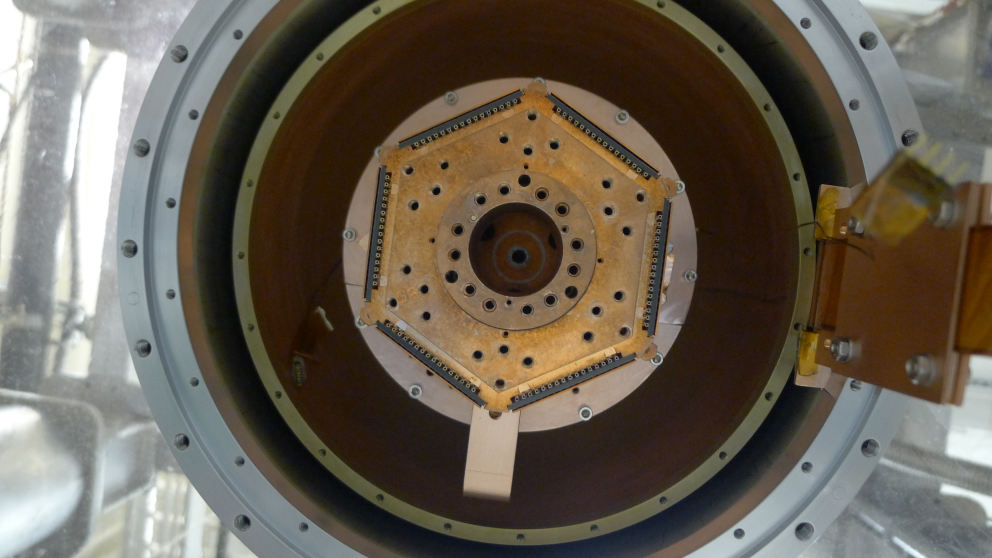
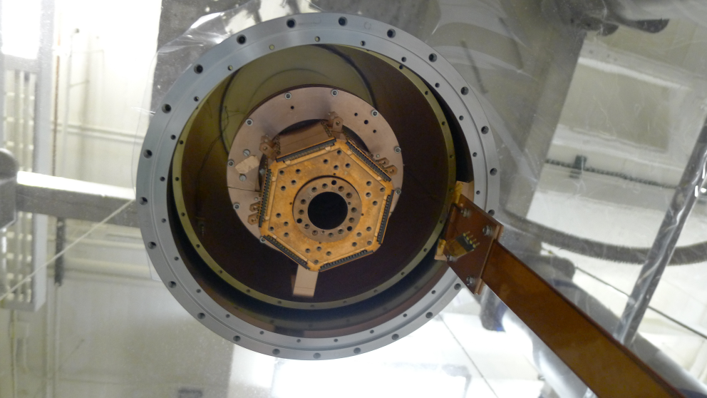
| Figure 3: Tower attached to 30 mK stage. |
|---|
 |
 |
| 1725 | Place nitrogen traps back in bath. Start cryocleaning mixture through nitrogen cold trap 2. |
|---|---|
| 1805 | Fill N2 cold trap full. |
| 1945 | Found a short during electrical check. Start investigating. Look at SQUET card & stripline pairs one-by-one. |