2012/04/14
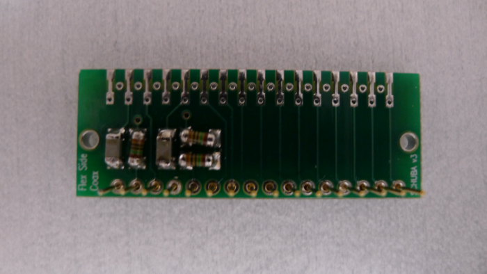
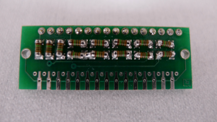
Feedback resistor chains have been desoldered from SCAB and attached to SCUHBA as shown in Fig. 1. An error in the design of SCUHBA v3 is visible on the Solder side: there is a missing trace between two resistors. This has been rectified with a solder joint, as shown in Fig. 1. SCUHBA passes electrical checks.
| Figure 1: Flexible Side Coax SCUHBA v3.1 Component (top) & Solder (bottom) Sides. |
|---|
 |
 |
SCUHBA Gerber files
Data sheets: 2.2 nF CoG/NP0 capacitor AVX 12065A222FAT2A & 10 MΩ metal film resistor Vishay Beyschlag MMA02040C1005FB300.
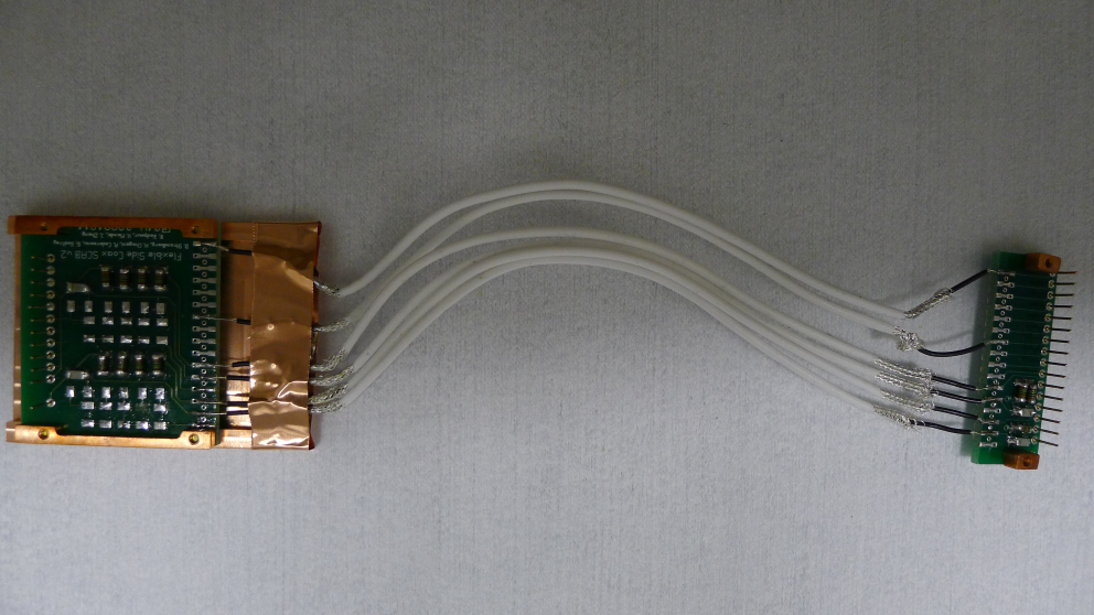
As feedback resistors are located on SCUHBA, six (rather than 8) low noise copper coaxial cables bridge gap between SCAB and SCUHBA, as shown in Fig. 2.
| Figure 2: Assembled Flexible Side Coax v3.1. |
|---|
 |
| Table 1: Tower Level Continuity Checks. | ||
|---|---|---|
| Side Coax | ZB1-1-9 | Flexible v3.1 |
| Tower Face | 5 | 2 |
| Qi feedback - Qi gate | 26 nS | 13 nS |
| Qi gate - Qi bias | <0.2 nS | <0.2 nS |
| Qi gate - ground | - | <0.3 nS |
| Qi bias - QET return D | <0.2 nS | <0.2 nS |
| Qi bias - ground | - | <0.3 nS |
| Qo feedback - Qo gate | 25 nS | 13 nS |
| Qo gate - Qo bias | <0.2 nS | <0.2 nS |
| Qo gate - ground | - | <0.1 nS |
| Qo bias - QET return D | <0.2 nS | <0.1 nS |
| Qo bias - ground | - | <0.1 nS |
| No shorts to ground! | ||