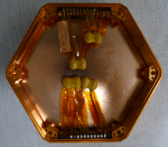
Two DIBs have been mounted in a 1 cm iZIP style housing. Each DIB features two 51 pF capacitors: one capacitor is soldered between Qi and QET Return A; the other between Qo and QET Return D. One rigid vacuum side coax is attached to one of the DIBs. The other DIB is for the flexible side coax.
| Figure 1: Assembled housing with 50 pF Capacitors. |
 |
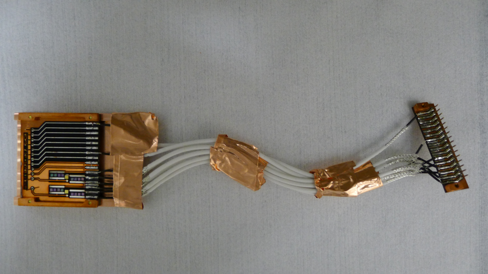
| Figure 2: Assembled Flexible Side Coax v1. |
 |
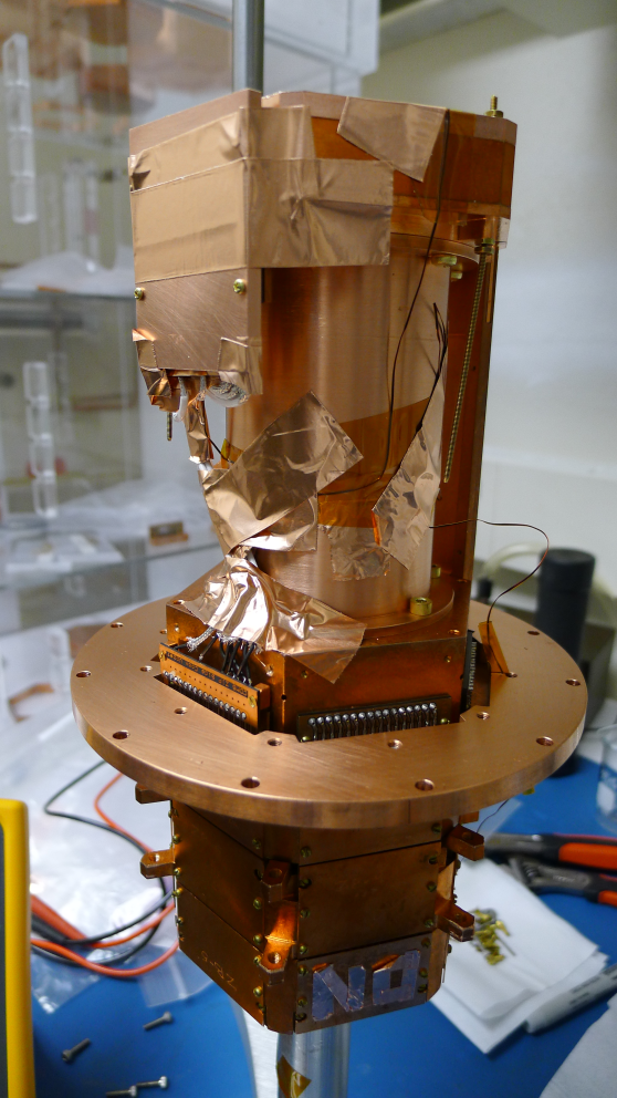
| Figure 3: Assembled Tower with Flexible Side Coax v1. |
 |
The first version of the flexible side coax comprises of SCAB and SCHUBA boards that have been extracted from a rigid vacuum side coax. Eight 6”-long, low noise copper wires (the same type as that used during Run 4) bridge the gap between pads on each board. Only charge pads (ie. pads 11-16), and QET return A & D (pads 1 & 7 respectively) have been connected.
To ground the braid, the shield from each cable is soldered to a piece of copper foil, which is attached with copper tape to the SCAB's back plate. At the SCHUBA end of the cables, the shield is simply taped to the surface of the tower.
RF shielding is provided by a copper back plate on the SCAB. Both the SCHUBA and the SCAB are separated from the detector housing and tower respectively by copper nut plated that have also been extracted from a side coax. The SCHUBA board does not feature a back plate.