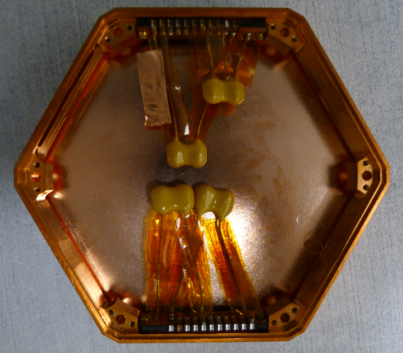
Two DIBs have been mounted in a 1 cm iZIP style housing. Each DIB features two 51 pF capacitors: one capacitor is soldered between Qi and QET Return A; the other between Qo and QET Return D. One rigid vacuum side coax is attached to one of the DIBs. The other DIB is for the flexible side coax.
| Figure 1: Assembled housing with 50 pF Capacitors. |
 |
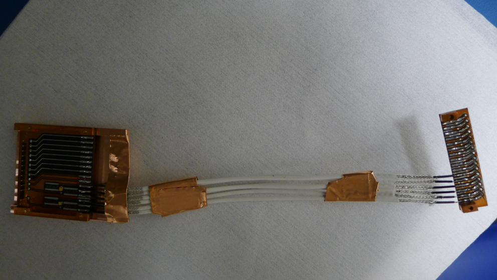
| Figure 2: Assembled Flexible Side Coax v1. |
 |
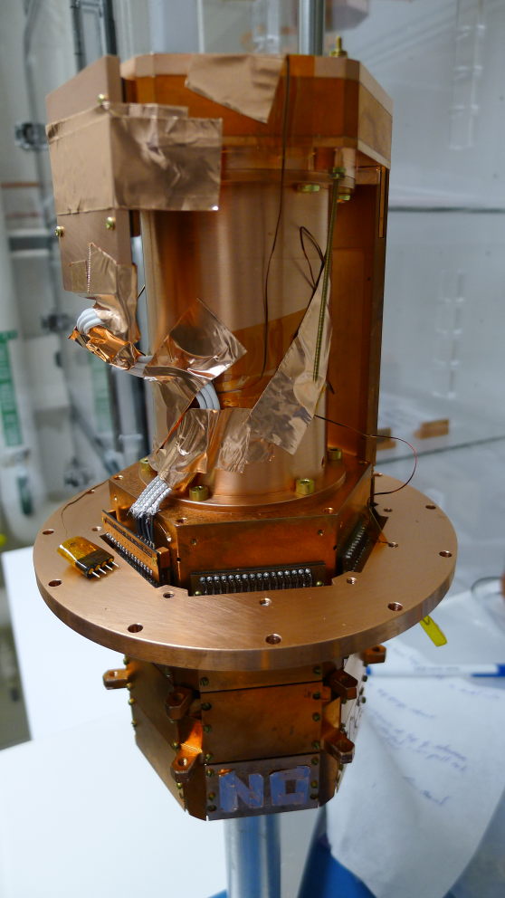
| Figure 3: Assembled Tower with Flexible Side Coax v1. |
 |
The first version of the flexible side coax comprises of SCAB and SCHUBA boards that have been extracted from a rigid vacuum side coax. Six 6”-long, low noise copper wires (the same type as that used during Run 4) bridge the gap between pads on each board. Only charge pads (ie. pads 11-16) have been connected.