Table of Contents
2009/12/07
Run Diary
| Time | Task |
|---|---|
| 11:21 | Measure ground noise. Take data Run 1. |
| 11:27 | Connected two braided cables for thermometry to the breakout box, with LS370 DB9 connector disconnected, ground noise doesn't change. |
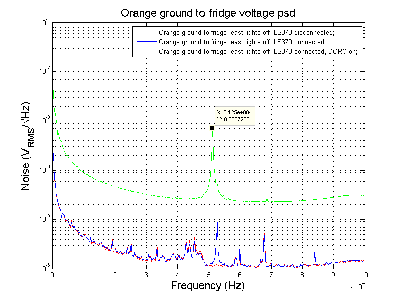
| 12:00 | Disconnect LS370 cable shield from the the DB90 connector. Noise peak at 52.5 kHz shifted to 52.75 kHz, magnitude reduced by ~1 uV. |
| 12:11 | Connect LS370 and take data Run 2. |
| 12:14 | Turn on DCRC. Take data Run 3. |
| Orange ground to fridge voltage psd |
|---|
 |
| matlab .fig file |
| DCRC contributes a lot to ground noise. The peak also shifted from 55.5 kHz to 51.25 kHz after decoupling LS370. |
| Time | Task |
|---|---|
| 12:29 | Check DCRC calibration constants. |
| DCRC calibration constants |
|---|
devd 1 1 Dev50.Ch00=2000 QinnerOffset Qinner bias is zero with this setting. [DAC] Dev50.Ch01=05B9 QinnerSlope The Qinner bias setting slope [uV/DAC] Dev50.Ch02=2000 QouterOffset Qouter bias is zero with this setting. [DAC] Dev50.Ch03=05B9 QouterSlope The Qouter bias setting slope [uV/DAC] Dev50.Ch04=2004 QETOffsetA Ch A QET bias is zero with this setting. [DAC] Dev50.Ch05=46B4 QETSlopeA Ch A QET bias setting slope. [10 pA/DAC] Dev50.Ch06=0808 SqOffsetA Ch A SQUID bias is zero with this setting. [DAC] Dev50.Ch07=2714 SqSlopeA Ch A SQUID bias setting slope. [10 pA/DAC] Dev50.Ch08=0802 LockOffsetA Ch A Lockpoint is zero with this setting. [DAC] Dev50.Ch09=1A14 LockSlopeA Ch A Lockpoint setting slope. [uV/DAC] Dev50.Ch0A=07FE DriveOffsetA Ch A Driver Offset is zero with this setting. [DAC] Dev50.Ch0B=084D DriveSlopeA Ch A Driver Offset setting slope. [-uV/DAC] Dev50.Ch0C=0843 NullOffsetA Ch A Offset Null is zero with this setting. [DAC] Dev50.Ch0D=0121 NullSlopeA Ch A Offset Null setting slope. [uV/DAC] Dev50.Ch0E=1FF9 QETOffsetB Ch B QET bias is zero with this setting. [DAC] Dev50.Ch0F=4840 QETSlopeB Ch B QET bias setting slope. [10 pA/DAC] Dev50.Ch10=0802 SqOffsetB Ch B SQUID bias is zero with this setting. [DAC] Dev50.Ch11=2700 SqSlopeB Ch B SQUID bias setting slope. [10 pA/DAC] Dev50.Ch12=0817 LockOffsetB Ch B Lockpoint is zero with this setting. [DAC] Dev50.Ch13=1A27 LockSlopeB Ch B Lockpoint setting slope. [uV/DAC] Dev50.Ch14=080E DriveOffsetB Ch B Driver Offset is zero with this setting. [DAC] Dev50.Ch15=083D DriveSlopeB Ch B Driver Offset setting slope. [-uV/DAC] Dev50.Ch16=08B5 NullOffsetB Ch B Offset Null is zero with this setting. [DAC] Dev50.Ch17=0127 NullSlopeB Ch B Offset Null setting slope. [uV/DAC] Dev50.Ch18=1FFB QETOffsetC Ch C QET bias is zero with this setting. [DAC] Dev50.Ch19=4867 QETOffsetC Ch C QET bias is zero with this setting. [DAC] Dev50.Ch1A=080F QETSlopeC Ch C QET bias setting slope. [10 pA/DAC] Dev50.Ch1B=269B SqOffsetC Ch C SQUID bias is zero with this setting. [DAC] Dev50.Ch1C=081A SqSlopeC Ch C SQUID bias setting slope. [10 pA/DAC] Dev50.Ch1D=1A02 LockOffsetC Ch C Lockpoint is zero with this setting. [DAC] Dev50.Ch1E=0804 LockSlopeC Ch C Lockpoint setting slope. [uV/DAC] Dev50.Ch1F=0873 DriveOffsetC Ch C Driver Offset is zero with this setting. [DAC] Dev50.Ch20=083C DriveSlopeC Ch C Driver Offset setting slope. [-uV/DAC] Dev50.Ch21=011C NullOffsetC Ch C Offset Null is zero with this setting. [DAC] Dev50.Ch22=2000 NullSlopeC Ch C Offset Null setting slope. [uV/DAC] Dev50.Ch23=482D QETOffsetD Ch D QET bias is zero with this setting. [DAC] Dev50.Ch24=07FD QETSlopeD Ch D QET bias setting slope. [10 pA/DAC] Dev50.Ch25=26EF SqOffsetD Ch D SQUID bias is zero with this setting. [DAC] Dev50.Ch26=080A SqSlopeD Ch D SQUID bias setting slope. [10 pA/DAC] Dev50.Ch27=1A21 LockOffsetD Ch D Lockpoint is zero with this setting. [DAC] Dev50.Ch28=07FC LockSlopeD Ch D Lockpoint setting slope. [uV/DAC] Dev50.Ch29=0859 DriveOffsetD Ch D Driver Offset is zero with this setting. [DAC] Dev50.Ch2A=08D1 DriveSlopeD Ch D Driver Offset setting slope. [-uV/DAC] Dev50.Ch2B=012C NullOffsetD Ch D Offset Null is zero with this setting. [DAC] Dev50.Ch2C=FFFF NullSlopeD Ch D Offset Null setting slope. [uV/DAC] Dev50.Ch2D=FFFF LEDSlope1 LED 1 current setting slope. [uA/DAC] Dev50.Ch2E=FFFF LEDSlope2 LED 2 current setting slope. [uA/DAC] Dev50.Ch2F=FFFF FBGain Feedback gain with PGA set to 1. Dev50.Ch30=FFFF OutGain Output gain with PGA set to 1. Dev50.Ch31=FFFF |
| Time | Task |
|---|---|
| 12:56 | Temperature goes up to 41 mK and plateaus. Ground fridge to orange ground. |
| 13:01 | Reset DCRC and wait for fridge to cool down. |
| 14:01 | Temperature bumps up again. |
| DCRC QET Bias Zeroing | |||
|---|---|---|---|
| QET | Decimal | Hex | QET bias (μV) |
| A | 36.9 | 20CC | ± 0.25 |
| B | 0.6 | 2003 | drifts |
| C | -0.1 | 1FFF | 0.5 |
| D | 1.5 | 2008 | drifts |
| Time | Task |
|---|---|
| 14:34 | Take psd of QET B noise. run004 to run010. |
| phB Superconducting noise psd at different output gains |
|---|
 |
| matlab .fig file |
| All noise peaks overlap perfectly. The peaks are from before the output gain. DCRC noise dominates. |
| Above plot in loglog scale |
 |
| Time | Task |
|---|---|
| 16:00 | Have been waiting for temperature to stabilize. But it doesn't. |
| Mixing chamber temperature |
|---|
 |
| Time | Task |
|---|---|
| 17:43 | Measure FB voltage change during SQUID lock. Take data run011 and run012. |
| Phonon FB voltage change during SQUID lock (open loop → non-inverting) |
|---|
 |
| In the above plot, FE gain of C was 6 and D was 7 if I remember correctly. Jeter suggested to close the loop at FE Gain = 0. I then redid the measurements shown below. |
| Phonon FB voltage change during SQUID lock (open loop → non-inverting) |
 |
| matlab .fig file |
| Phonon modulation curves |
|---|
 |
Data List
All data and figures can be found at http://www.hep.umn.edu/cdms/cdms_restricted/K100/runs/run001/20091207/
| Measure the PSD of the voltage between the orange and the fridge |
|---|
| Time | Run # | Comment |
|---|---|---|
| 11:25 | 1 | Orange ground to fridge, east lights off, LS370 disconnected. |
| 12:11 | 2 | Orange ground to fridge, east lights off, LS370 connected. |
| 12:16 | 3 | Orange ground to fridge, east lights off, LS370 connected, DCRC on. |
| run004 to run010 settings |
|---|
| MC T = 41 mK; QET B: FE Gain = 7, FB Null = 7.09 mV, Driver Offset = -0.03 V, SQUID Bias = 93.04 uA, Lockpoint = 3.30 mV, QET Bias = 0.6 uA; Fridge grounded to orange ground; |
| Time | Run # | Comment |
|---|---|---|
| 14:30 | 4 | QET B Output gain = 1. |
| 5 | QET B Output gain = 2. | |
| 6 | QET B Output gain = 3. | |
| 7 | QET B Output gain = 4. | |
| 8 | QET B Output gain = 5. | |
| 9 | QET B Output gain = 6. | |
| 10 | QET B Output gain = 7. |
| run011 settings |
|---|
| MC T = 37 mK; QET C: FE Gain = 0, Output gain = 1, FB Null = 0.02 mV, Driver Offset = 0.00 V, SQUID Bias = 76.63 uA, Lockpoint = 2.38 mV, QET Bias = 0.1 uA; Fridge grounded to orange ground; |
| Time | Run # | Comment |
|---|---|---|
| 17:43 | 11 | QET C open loop to non-inverting. |
| run012 settings |
|---|
| MC T = 37 mK; QET D: FE Gain = 0, Output gain = 1, FB Null = 0.02 mV, Driver Offset = 0.02 V, SQUID Bias = 68.91 uA, Lockpoint = 1.57 mV, QET Bias = 0.1 uA; Fridge grounded to orange ground; |
| Time | Run # | Comment |
|---|---|---|
| 18:23 | 12 | QET D open loop to non-inverting. |
| Channel | FE Gain | Output Gain | Feedback Null (mV) | Driver Offset (V) | SQUID Bias (uA) | Lockpoint (mV) | QET Bias (uA) |
|---|---|---|---|---|---|---|---|
| A | 0 | 1 | 0.02 | 0.02 | 90.01 | 3.20 | 36.9 |
| C | 0 | 1 | 0.02 | 0.00 | 76.34 | 2.38 | -0.1 |
| Time | Run # | Comment |
|---|---|---|
| 2009/12/08 14:33 | 13 | QET A open loop to non-inverting. |
| 14 | QET C open loop to non-inverting. |