−Table of Contents
Installing the Polyethylene and Lead Shield
adapted from Alex Codoreanu, June 2012
General Description and Safety Recommendations
The Gamma Lead Shield, in combination with the neutron polyethylene shield has been designed in order to minimize the background readings in the lab. They are both mounted on a 2 cart system. The short side of the polyethylene neutron shield along with the corresponding frames is to be kept on the carts at all times unless different bottom shield setups need to be tested. This will save installation time and labor. The carts are stored in the storeroom next to the lab. The remaining polyethylene and lead sheets are stored in various other parts of the lab and/or in the LIGO lab. Move one cart at a time and adjust them into place. Once placed in the desired location, clamp the carts together for further stability and begin installation.
The minimum amount of people needed is 2 but 3 people are recommended. As this is a somewhat physically strenuous activity a 4th person is handy in order to take breaks and maintain the installation schedule.
Safety Recommendations
The overall assembly is in excess of 4000 pounds and as such general safety guidelines should be observed at all times.
NEVER:
- Pull yourself up on the frame assembly for a better view of your workspace.
- Reach under the frame for a dropped tool or personal item. If you drop something, use a meter stick or other implement to recover your lost item.
- Move the carts by pushing on the frame of the Lead Shield. While it is bolted on this is not recommended as it can put additional torque on the screws which increases the chances of a structural failure at a later time.
- Lift more than 50 pounds alone. This applies to the installation of the long side of the polyethylene shield. The Lead Shield has been designed so that no single panel weighs more than 40 pounds. The panels present another problem as they are very malleable and 2 people might be needed depending on the individual’s ability to handle the soft metal in the proper way.
- Handle the lead panels without proper hand protection. Even when wearing gloves you should always wash your hands, forearms and then face after working with them.
- Lift just with your arms and leg. This will save your back as there are many panels to be installed.
An important thing to always keep in mind is that you are working with somebody else and you need to always be aware of their location as you move around with the poly or lead panels. At times you will be carrying them in front of you and your vision might be impaired. Be aware of them as well as other obstacles that might be present in the lab. When installing the lead and aluminum panels always be aware of where their fingers are before pushing the panels in their locations.
Bottom Shield Assembly
The bottom shield consists of a total of 24 lead pieces. 8 pieces are cut to 26”x10”, 8 pieces are cut to 42”x10”, 4 pieces are cut to 12”x22” and 4 pieces are cut to 14”x22”. The 26”x10” cut pieces fit under the short side of the polyethylene shield and are attached to the plywood on the cart with a bolt in order to lock them in position. The 42”x10” pieces fit in between the previous pieces and the long side of the poly shield will go over them. The 12”x22” and the 14”x22” pieces have had their corners removed in order to accommodate the support posts of the carts. The only thing to keep in mind is that the seams of successive layers do not overlap. This is accomplished by alternating the left/right location of the pieces. To finish off assembly simply cover the lead with the similarly cut aluminum covers. At this point you should also add the 22”x22” poly pieces that fit in between the supporting posts. Before moving on, make sure that 42”x10” pieces are as flush as possible as this will interfere with the installation of the lead shield frame. If that is the case, you will have to remove the long side of the poly shield in order to remedy the shift in position.
If you are testing shielding options in which the bottom shield is not necessary, there are .5” thick pieces of marine grade plywood that are cut in the same way and fit in the same manner. Remember to still cover the outer perimeter with aluminum as the poly has been cut to exactly fit over the aluminum and bottom shield. This is VERY IMPORTANT as the rods on the support posts have not been designed as load bearing implements.
Polyethylene Neutron Shield Assembly
There are 2 different sizes to the overall lengths of the Neutron Shield which are referred to as the Long and Short sides. The names are not misleading. Not all layers are comprised of single panels and this is where some confusion might arise. There are 2 different identification systems in place on each of the panels.
The first is comprised of yellow sticky notes attached to each of the panels. This system identifies one of the faces as A, B, C, or D and a numeric identifier. Thus, all A5 pieces belong to the same layer.
The second identification system consists of black sharpie alphanumeric id tags on the poly itself. The letters denote the layer to which all individual pieces belong. The short side has a single letter identifier while all long side identifiers are preceded by ‘L’. For example: C1, C2 and C3 are the 3 pieces of a single layer on the short side while LC1, LC2 and LC3 are the 3 pieces of a single layer on the long side. This is just an example, do not expect the C layers to have only 3 pieces. If there is no identifier then the layer you are looking at is a single piece layer, which should be obvious. In order to prevent the layers from tipping over use the provided paper clips as each layer is attached. While it is not a hazard, it is recommended to not fully finish one side before moving on to the next side.
No matter which identifier you end up using, it is important to make sure that the first and last layers are comprised of single pieces. Keep this in mind as you assemble the polyethylene neutron shield.
Frame Assembly
The overall frame consists of 4 pieces. They are all the same size and when properly attached, each face should have one seam with protruding bolts on which to fit the cover plates as seen in the picture below.
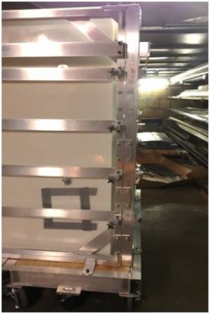
When properly installed each face should have one corner that looks like this. You should figure out the orientation and placement of each of the panels before placing them on the carts. As it can be observed from picture the bottom of each frame panel has 2 protrusions, which are to be bolted into the frame. This is not enough to keep them locked in place and make sure that, before walking away, the frame is attached in another manner as well to the cart. If you do not have to do a full install with a custom bottom shield, 2 of the frame panels should already be installed on the long side of the poly shield and bolted to the bottom of the cart as well as to the support posts. The following description of installation assumes that you have to install everything.
Installation of Gamma Shield
- Decide an orientation and position for the 4 frame panels and choose the two that will go on the long side of the poly.
- Place the 1st frame panel in front of the long side of the poly using 2 people. Have one person support the panel at all times while the other person/s install the support brackets and bottom support screws.
- Repeat for the opposing side, in front of the other long side of the poly.
- Place a frame panel in between the already installed frame panels. Have one person support it while the other person/s install the L brackets on the corners. There is only one orientation possible for the L brackets. AFTER the L brackets have been secured, install the bottom support screws.
- Repeat step 4 for the last frame panel.
- Attach the temporary securing brackets to the last 2 panels you have just installed.
If you can’t fit the panels together, you should check the bottom shield to ensure that it’s not sticking out. If the bottom shield has shifted it will be impossible to fit the 4 frame panels together to form a single structure and unfortunately, you might have to remove the rest of the panels and the long side of the poly shield in order to readjust the position of the bottom shield. Check for other possibilities before resorting to this.
- Now that you have installed the frames on the carts it is time to secure them together. On each side one of the corners is going to have screws protruding from the frame you area in front of and the one perpendicular to it ( to your right). You can fit 3 double securing plates and 1 single securing plate over each of them. Place all of them on before securing the nuts on them. When locking the nuts, use the drill on the 20 setting with the 3/8” attachment. DO NOT use the drill with a higher setting than 20 as you could unscrew the threaded bolt from the frame and it will very difficult to put it back in.
You have just finished installing the frame for the lead shield and it is now time to install the lead shield. The shield itself is comprised of 5 layers of lead that are sandwiched between 3 aluminum layers. The aluminum layers are comprised of 2 panels and the 5 layers of lead are comprised of 2 layers made up of 3 panels of 11.5”x48” and 1 panel of 11”x48” while the other 3 layers are made up of 5 panels of 9.5”x48”. The layers have been designed so that you can alternate between each layer so that no seams overlap. Also when installing the layers do not finish one face before moving on to the next one. Only set up one sandwiched layer of aluminum at a time on all 4 sides of the frame before moving on to the next one.
EACH LAYER HAS A LEAD PANEL WHICH HAS BEEN ADJUSTED IN SIZE IN ORDER TO MAKE THE INSTALL EASIER. ONLY USE ONE ORANGE TABBED PANEL PER LAYER.
- Put in 2 aluminum panels inside one of the sides of the frame. Choose one of the 2 possible lead layer configurations and put them in. They are not strong enough to support their own weight so one of you must hold them in. You can place large paper clips over the top of each panel in order to hold it in place. The clips can hold up to 3 layers safely in place.
If one of the panel is deformed simply walk back and forth over the panel a few times and the lead panel should be fine to use again. Finish the layer and remember to put a layer on all the sides before moving on to the next layer. It is easiest to choose the same layer configuration for all the same faces of the frame as it will make it easier to keep track of which layer should be used for the following layer.
- At this point you should have the first layer on all the sides. This layer should be of an alternate design that the one preceding it. This ensures that no seams overlap in the shield. Same procedure should be followed as in the previous step 8.
After the first couple of layers it will get difficult to place the ensuing layers. This is because of the bowing of the lead sheets. You can use a strong piece of aluminum or something else that works and push the layers inside the channels to make room for the next layers.
- Once all the layers have been installed the aluminum u-channel bars can be mounted in order to distribute pressure across the entire face of the shield. Each face has 4 bars which are secured and fastened with the threaded screws pictured below. It is important that they are all adjusted the same depth to prevent further deformation of the lead. You can use a ruler for this.
- Congratulations ! You are almost done. All that is left now is to install the top shield.
- The top shield is configured to be installed on the top support beam of the cart in such a fashion as to cover the gap between the shield and the K100 Dilution Refrigerator. First install the aluminum support piece and attach the 2 support screws. The top face of the Al plate has had the screw hole counter sunk so that the screws are flush. Make sure that this is the top face when you install it. After installing, simply stack the similarly cut poly pieces and lead pieces.