Table of Contents
Complex Impedance Measurements
Complex impedance measurements involve applying an AC QET bias (test signal) and observing the response signal.
TES Resistance
There are three regimes in which we can measure TES resistance: superconducting, transition, and normal. In all cases the relationship between the QET bias current and the current in the TES results from the simple current-divider TES circuit:
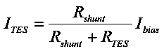
which can be rearranged

and differentiated
 | (Equation 3) |
The above is for the general case in which the TES resistance is not considered to be constant. The only quantity assumed constant is the shunt resistance. The task is to express the TES resistance in terms of known quantities: the AC input, the AC output, and the shunt resistance. We do not assume we can know the TES current, so this term must be canceled somehow.
Normal/Superconducting case
If the TES is in the normal state or in the superconducting state its resistance is constant, so we can apply the constraint
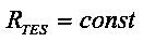
to Equation 3 and get

or
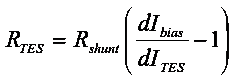 | (Equation 6: TES resistance in normal or superconducting case) |
The equation above is the desired result: the TES resistance as a function of the known input and output and shunt resistance. In the superconducting case this is actually the parasitic resistance in series with the TES. In the normal state this gives the normal TES resistance plus the parasitic resistance.
Transition (biased) case
If the TES is in transition then we assume that electrothermal feedback is working to keep the TES at its transition temperature. The current through the TES will be such that the power dissipated by this current is the constant amount necessary to heat the TES above the crystal temperature. So we impose the constraint

Differentiating the above yields

and solving for the TES current,
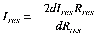
Substituting into Equation 3 yields

which simplifies to
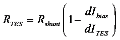 | (Equation 12): TES resistance in transition case |
Expected output in the two cases
Equations 6 and 12 can be rearranged to show what output we expect in the two cases:
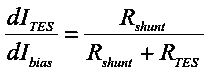 | (Equation 7: Output with respect to input in normal/superconducting case) |
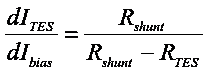 | (Equation 13: Output with respect to input in transition case) |
Note that in the transition case the response is typically negative, since the TES resistance is typically larger than the shunt resistance. This manifests as a 180-degree phase shift in the TES waveform versus the test signal input. This points out an important point in using these equations: if the output is out of phase then dIbias/dItes is negative, and should be entered in Equation 12 as a negative number.
It should also be pointed out that the TES can be in transition without a phase shift, if it is biased at a point where the TES resistance is smaller than the shunt resistance.
Adjustment to include parasitic resistance
If we assume there is a non-zero parasitic resistance in series with the TES resistance, the current-divider equation becomes
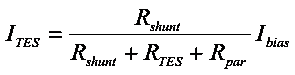
Following the same exercise as before produces the following:
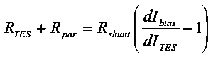 | (Equation 15: Normal/superconducting case, Rtes constant) |
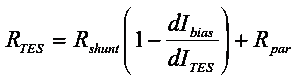 | (Equation 16: Transition case, Ptes constant) |
In the superconducting state the TES resistance is zero so Equation 15 would yield the parasitic resistance. In the normal state Equation 15 can be used to get the normal TES resistance if the parasitic resistance has already been calculated. The parasitic resistance is also a correction when calculating the transition state resistance with Equation 16.
Calibration factors to calculate dIbias and dItes
The AC bias is introduced by use of the DCRC signal generator which produces a triangle wave. Frequencies of 100-500 Hz are appropriate for this calculation. The peak-to-peak voltage can be set using the DCRC. To know the peak-to-peak current you need to know the bias resistance. These can vary with DCRC; for the DCRCs we used the values are
| DCRC | Rev | Bias resistance |
|---|---|---|
| DCRC55 | RevC.1 | 10 kΩ |
| DCRC50 | RevC.1 | 10 kΩ |
| DCRC33 | RevC.1 | 1 kΩ |
Then dIbias [App] = dVbias [Vpp] / Rbias [Ω].
The output in the pulse viewer is in Volts. To know the peak-to-peak TES current you need to know the appropriate gain factors. These include the feedback resistance, the loop gain, and the DCRC amplifier gains (fixed and variable).
| Feedback resistance | 1233 Ω |
|---|---|
| Loop gain | 10.5 |
| DCRC fixed gain | 2 for RevC.1, 5 for RevC |
| DCRC variable gain | 1,2,4,8 for RevC.1, 1,2,3,4,5,6,7 for RevC |
| Typically used DCRC variable gain | 8 for RevC.1, 3 for RevC |
Then dItes [App] = dVtes [Vpp] / (Rfeedback [Ω] * Gloop * Gdcrc-fixed * Gdcrc-variable)