Table of Contents
Testing the Poly-Lead Shield with S34 Background Gamma Spectra
The following wikipage is dedicated to the study of the two main topics: 1) the incident gamma-ray background spectrum of Cryogenic Dark Matter Search (CDMS) Detector Testing Facility located in room s34 of Tate Hall at the University of Minnesota, and 2) the testing of the new poly-lead shield to be used with k100 fridge.
This study will use a p-type high purity germanium (HPGe) detector from Princeton Gamma-Tech. This detector has an energy range of 40 keV-10 MeV and has a resolution of 820 eV-2.3 keV. For more information on the detector, please see the detector user manual here: gamma_and_xray_detectors_rev1_200507.pdf.
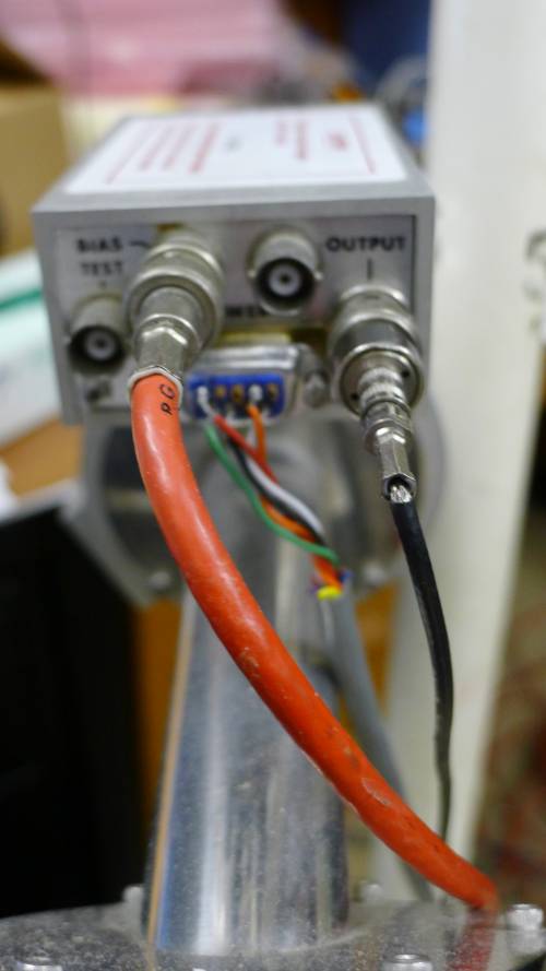
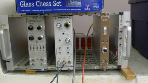
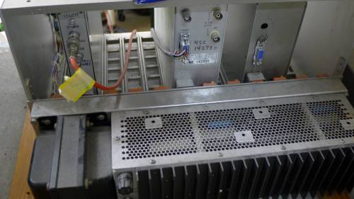
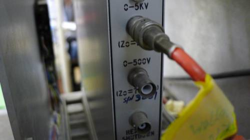
| Figure 0: HPGe crystal electronic setup | |
|---|---|
 |  |
 |  |
S34 Background Gamma Spectrum
| Figure 1: Gamma Spectrum of S34 Background after 16 hours (10/10/2011) |
|---|
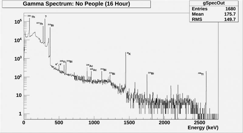 |
Figure 1 above shows our first attempt of the gamma background spectrum of our lab s34. It is believed that the odd shape of the 0-400 keV region is due to not allowing enough time between applying the voltage bias to the detector and beginning the run. Similar results were found when the run was started immediately after the bias was applied. These high levels of noise at low energies are due to the operational voltage of the detector not yet reaching a steady value. For more information on the issue, see section 3-5 of the detector user manual (link posted above). As of now it seems that two hours is an acceptable waiting time before starting a run.
The peaks in the background have mostly been identified as the daughter products of Th-232, U-238, K-40, and U-235 decay. These are considered naturally occurring and unavoidable sources that are most likely present in the walls and floor of s34.
| Figure 2: Gamma Spectrum of S34 Background after 18 hours (23/11/2011) |
|---|
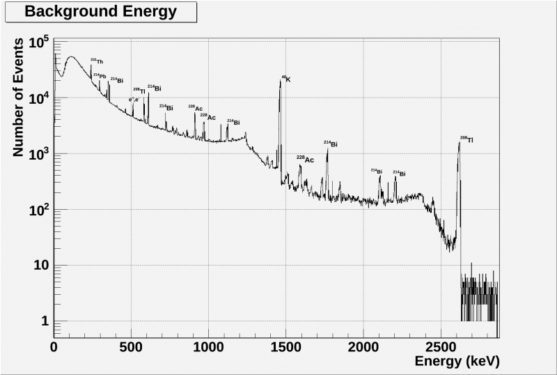 |
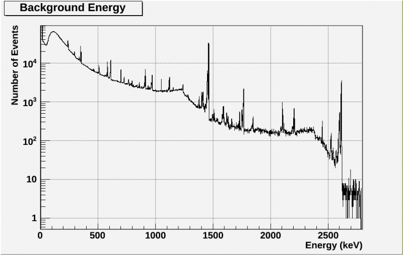
Figure 2 above and Figure 3 below both show the background without the odd shape at low energy due to the bias voltage. Neither have been normalized. The 24 hour background of Figure 3 will be used to compare to the runs with the poly-lead shield to see how it affects the gamma background.
| Figure 3: Gamma Spectrum of S34 Background after 24 hours without shield (07/06/2012) |
|---|
 |
Lead Shield
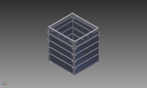
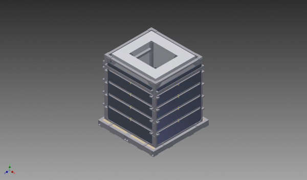
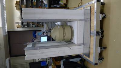
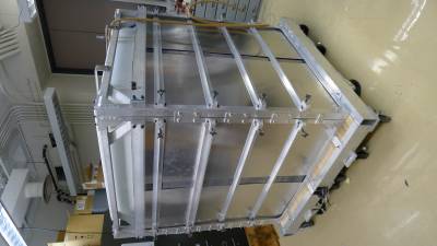
The lead shield is made with four layers of 1/8“ thick lead sheets on the sides and bottom of the detector. It is attached to the poly shield with an aluminum frame. You can find the motivation for the lead shield here: k100yshield.pdf. Below are the designs made by Pete Ness from the machine shop for the lead shield that will surround the poly shield protecting K100. Also included are photos of the HPGe crystal within the poly shield with lead shield base and the completed poly-lead shield. For more information on the poly shield, please see the wiki page neutron_shield, or Roxanne Radpour's thesis on the topic Design, Construction and Assessment of a Neutron Shield for CDMS Test Facilities .
  |  |  |
Lead Shield Predictions
| Figure 4a: Predicted Event Rate as a Function of Photon Energy for Different Thicknesses of Lead Shielding. | Figure 4b: Energy dependence of gamma-ray interaction processes in Lead |
|---|---|
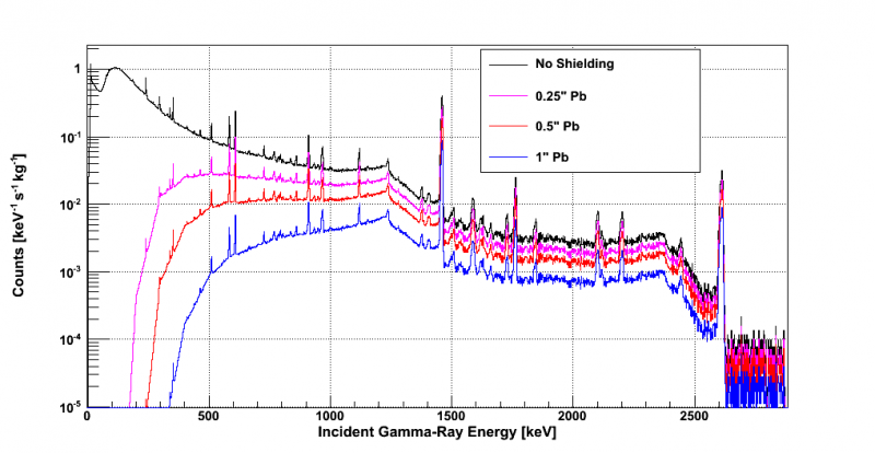 | 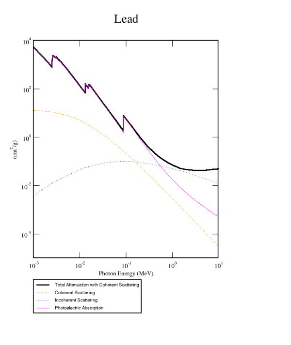 |
Figure 4a above shows an analytic prediction of the effects of lead shielding on the incident gamma-ray background. This simple prediction considers only the photoelectric absorption in the lead, which results in the large drop in events below about 750 keV. It neglects Compton scattering and other effects where a gamma might lose a portion of its energy in the shield before depositing a lower energy in the detector. This prediction also ignores the presence of Radon in dust inside the shield that would contribute to the lower energy event counts. For these reasons it is expected that actual results will have much higher low energy counts. This figure comes from Brief Feasibility Study of Gamma Shield for K100 by Hassan Chagani and Allison Kennedy k100yshield.pdf.
Figure 4b shows the energy dependence of several gamma interaction processes in Lead. Note that for the significant energy range (roughly 40-2700 keV) photoelectric absorption is prominent in the 40-500 keV energy range, whereas incoherent (Compton) scattering is prominent above 500 keV. This figure comes from XCOM: Photon Cross Sections Database.
Lead Shield Data
| Figure 5: Comparing Gamma Spectrum of S34 Background with full shield and with no shield (07/06/2012 and 16/06/2012) |
|---|
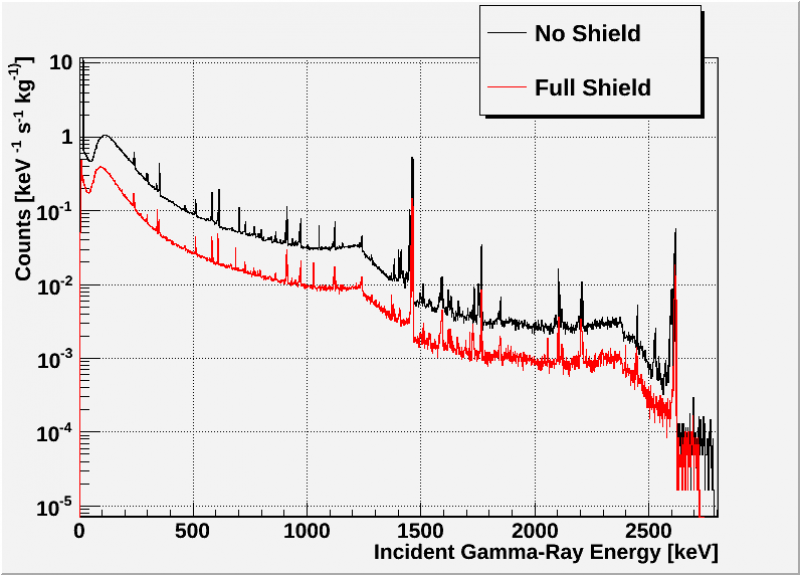 |
Figure 5 above compares the shielded and unshielded gamma spectra. It can be seen from this figure that the shield reduces the count number by a bit less than half a magnitude. When comparing to the rough prediction in Figure 4, it is important to note that the actual shield only covers the sides and bottom, where as the prediction assumes complete lead coverage. Still, we are hopeful that other alterations to the shield might improve the overall decrease in counts. Some of these alterations are addressed in the next section.
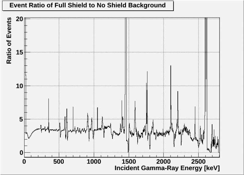
Figure 6 below gives a rough estimate of the ratio shielded count divided by unshielded count as a function of incident gamma energy. Due to slight changes in liquid Nitrogen levels and thus detector temperatures, as well as voltage bias, it is very difficult to get spectra peaks to completely line up. Therefore this figure takes an average of each count number and the count numbers of the closest four bins and uses this value to calculate the ratio. Despite this, this method still results in ratios that do not accurately demonstrate the change in count number for large peaks, such as the K-40 and Tl-208 peaks. Treating these large jumps and dips in ratio as noise, we can see that overall there is a ratio of roughly 3.5 for low energies. This ratio value drops as energies increase, with a value of roughly 2 at the high energy limit of our spectrum.
| Figure 6: Ratio of Gamma Spectra of S34 Background: Full shield/ No shield (07/06/2012 and 16/06/2012) |
|---|
 |
Shield Alterations
The preliminary shield tests above show that the poly-lead shield reduces the background by almost half a magnitude. It is thought that this could be improved by addressing some of the design issues of the shield. Due to the buckling of the thin, flexible, lead sheets, there exist overlaps between sheets in each layer which make the shield bulkier than expected, as well as leaving some gaps that cannot be fixed by readjusting the sheets. A larger issue is the open top of the shield. Unfortunately this issue is more difficult to solve since any shield top must fit around the k100 fridge and provide sufficient coverage. This would require at least two pieces of lead that fit around the outside of the dewar as well as pieces of lead above layers of poly within the dewar to block gammas and neutrons from reaching the detector.
Before addressing these design issues, we first wanted to use the shield to study the lab background. In particular, we wished to explore a possible non-homogeneity of our background, which might suggest a background source or contaminant. Similar tests have been done with lead bricks and the same detector by Andrew Emerick and Karley Weir. Their results are included here: mxp_gefinal_report.pdf. They concluded that there was no directional component to the spectrum. We wish to verify some of these results with the shield.
Removing Shield Bottom
Since Th-232, U-238, K-40, or U-235 are present in many building supplies such as cement, it is fair to assume the presence of these isotopes in the walls and floor of s34. The floor is of particular concern since it is cement and relatively close to the detector. Therefore we decided to test the affects of the shield bottom by comparing the full shield run to a run with the bottom of the shield absent. Particle board was used in place of the lead, simply as support to the poly shield.
| Figure 7: Comparing Gamma Spectra of S34 Background with full shield and shield without bottom (16/06/2012 and 21/06/2012) |
|---|
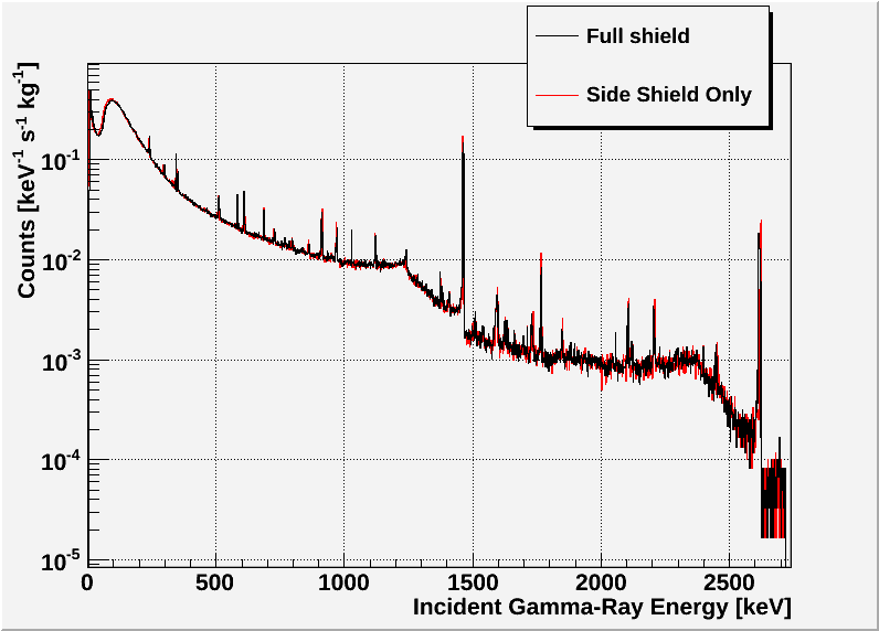 |
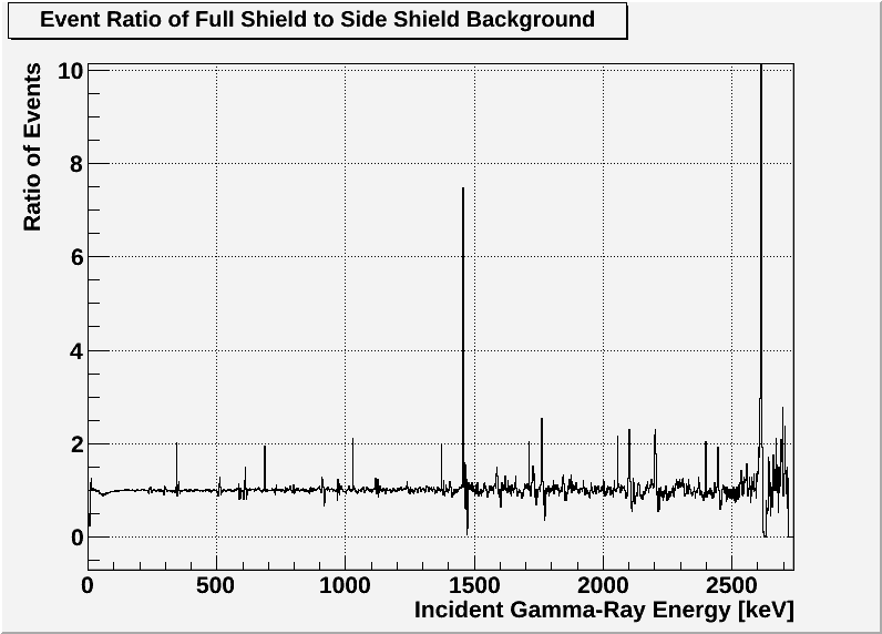
As can be seen in Figure 7, there is no significant difference between a run with the full shield and a run with the shield bottom removed. Figure 8 verifies this result with a gamma spectra ratio of roughly one, suggesting a negligible change in event counts between runs (recall that the peaks in this figure are most likely due to an inability to perfectly line up bins, and should thus be ignored). This suggests that the bottom shield does little work in shielding the detector. This is somewhat surprising, and has caused us to start considering the ceiling as a possible source for the majority of the background. The future goal of constructing a poly-lead top shield will be discussed later. Tests done by Andrew Emerick and Karley Weir found that the shield bottom did have a significant affect on the event count, although the much greater shield thickness must be considered.
| Figure 8: Ratio of Gamma Spectra of S34 Background: Full shield/ Bottomless shield (16/06/2012 and 21/06/2012) |
|---|
 |
Additional Shield Layer
As mentioned earlier, the buckling and overlapping of the lead sheets has resulted in a bulkier shield with gaps between lead where gammas could enter. To combat this one lead sheet from each layer has been trimmed so that each sheet fits without any overlap. In general this reduces the amount of cracks, but to increase the shielding (especially in places where the lead doesn't fit tightly against the adjacent pieces) an additional sheet of lead (also trimmed) was included. This extra layer was made from the remaining unused pieces of the shield. Since there was not a sufficient amount to make a complete fifth layer, one side simply has three 11.5” pieces which cover the cracks in the previous layer. The sheets have been placed such that each gap is covered by at least 0.5“ of lead. A new run was performed on 27/06/2012 with the new shield. The results are shown below.
| Figure 9: Comparing Gamma Spectra of S34 Background with standard shield and shield with fifth layer (16/06/2012 and 27/06/2012) |
|---|
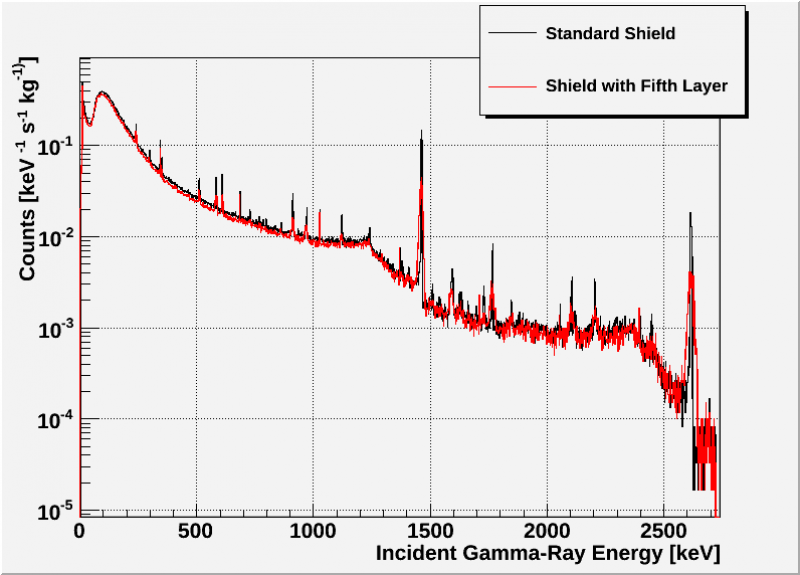 |
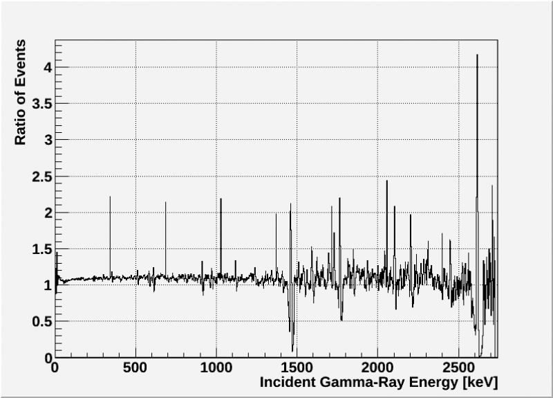
Figure 9 compares the spectrum of the standard four-layer shield to the trimmed five-layer shield. It can be seen by eye that there is a slight reduction in the event count with the new fifth layer shield. It appears as though the peaks have been significantly reduced in magnitude, though they have actually just been spread out. This is believed to be an unfortunate side effect of switching out the cord connecting the detector to the voltage bias. Figure 10 verifies the slight change in event count between the two runs. It gives a spectra ratio of roughly 1.1, suggesting a small but measurable change in event count.
| Figure 10: Ratio of Gamma Spectra of S34 Background: 5-Layer Shield/ Standard Shield (16/06/2012 and 27/06/2012) |
|---|
 |
Adding a Shield Top
Throughout our tests on the s34 background and the poly-lead shield, it has become increasingly obvious that a shield top must be made to determine the directionality of the background spectrum as well as reduce the background of the k100 fridge. Creating this shield top is an ongoing project, which requires cutouts of the pipes leading to the IVC within the k100 dewar as well as a new order of lead. Updates and results to be posted as they occur.
We have performed tests that remove the bottom of the shield (which have been shown to have little impact on the spectrum reduction) and used it as a top shield. This was done by setting wood boards across the polyshield and setting the lead strips on that in such a way to reduce the number of overlapping cracks. We then began more testing. As mentioned earlier, we have had issues with the detector warming up and giving us double peaks. This especially occurs with the first runs of the detector as it is difficult to determine how full the detectors LN2 dewar is. That is why we were not surprised when we got the following spectrum.
| Figure 11: Gamma Spectrum of S34 Background after 24 hours. Shield: top, no bottom.(25/09/2012) |
|---|
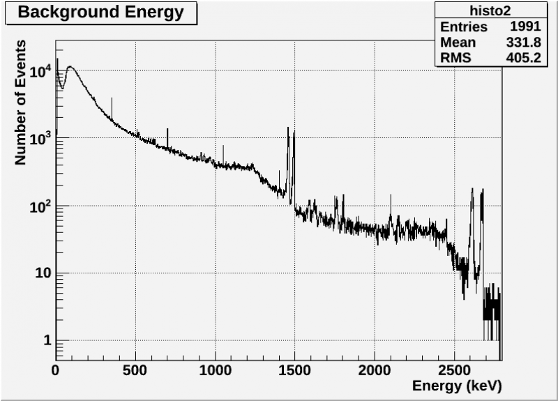 |
Please note that on the 21st a transfer of roughly 25L was performed, with another transfer of 25L performed on 23rd. The simulation was then started on the 24th (giving the dewar plenty of time to cool) and finished in 24 hours. Since we believed that these double peaks were due to the detector being too warm we did some more transfers. On the 25th we performed two 25L transfers and on the 26th we performed another 25L transfer. Please note that when we were able to measure the dewar weight to determine how full the dewar was, we found that two transfers filled the dewar from almost empty, and that the dewar only lost about 3L per day. However, the transfers when the dewar is in the shield are more difficult to gauge because a longer hose is used (wasting more LN2) and it is more difficult to determine if the dewar is overflowing.
After the transfer on the 26th another run was started which lasted 24 hours. Here are the results:
| Figure 12: Gamma Spectrum of S34 Background after 24 hours. Shield: top, no bottom.(27/09/2012) |
|---|
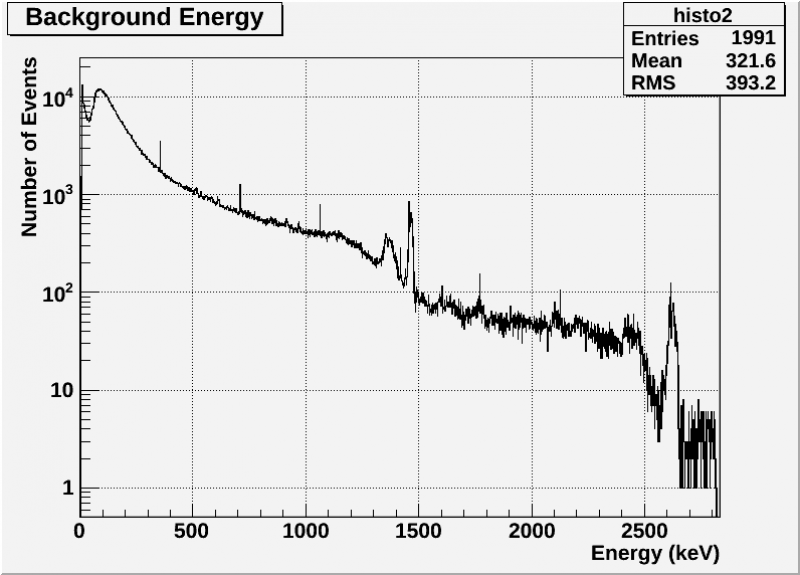 |
The peaks from the previous run have not vanished, but instead seemed to morph into weird Compton edge-esque bumps. We wanted to check to see if the weird bumps were due to the detector getting too warm yet again, so that day we started yet another run without doing another transfer. Here are the results:
| Figure 13: Gamma Spectrum of S34 Background after 24 hours. Shield: top, no bottom.(28/09/2012) |
|---|
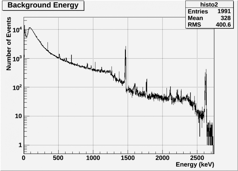 |
The results look great, but we have no idea why the bumps went away. Was it possible that the bumps from the 28/09/2012 data due to the detector being too cold?
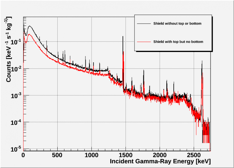
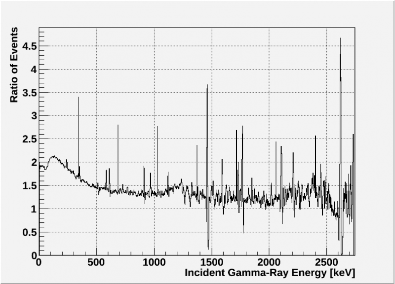
After this run with the top but without the bottom we did another run with neither a top nor bottom shield to compare. Here are the results.
| Figure 14: Gamma Spectrum Comparison of S34 Background after 24 hours. (28/09/2012 and 02/10/2012) |
|---|
 |
| Figure 15: Gamma Spectrum Ratio (No bottom data/No top or bottom data) of S34 Background after 24 hours. (28/09/2012 and 02/10/2012) |
|---|
 |
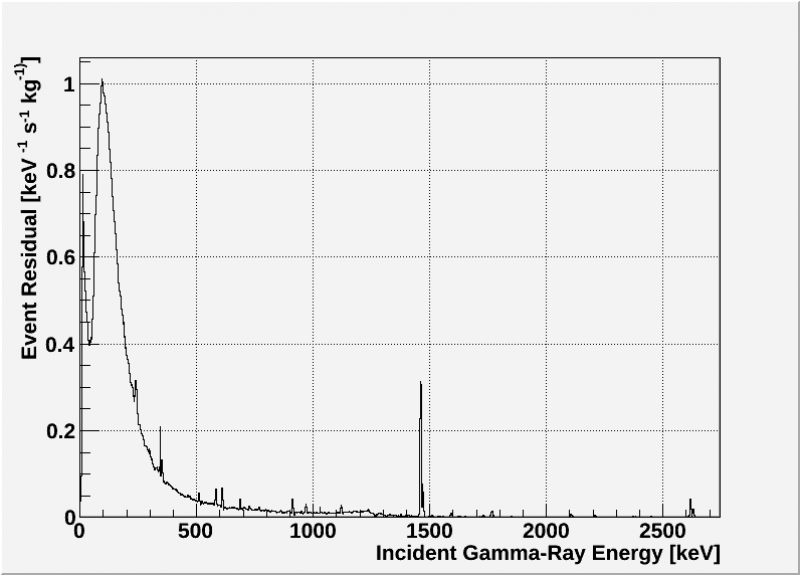
| Figure 14: Gamma Spectrum Residual of S34 Background after 24 hours. (28/09/2012 and 02/10/2012) |
|---|
 |