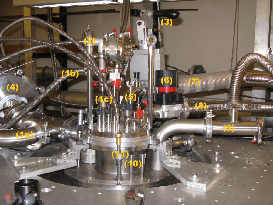
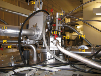
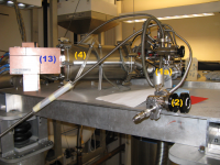
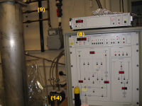
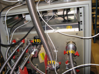
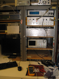
Kelvinox 100 Components
Note: Number labels not yet accurate. Some editing still needed.
- 1K Needle Valve (5) Controls flow rate of Helium from the main bath () to the 1K Pot (17). Used to add He4 to 1K Pot () which can then be pumped on by the He4 pump () to reduce the temperature.
- 1K Pot Used to pump on liquid He to reduce temperature. Contained in IVC (19).
- 1K Pot Speedivalve Connects HE4 pump () through back of Intelligent Gas Handling System (IGH) (8) to 1K Pot (5).
- Breakout Box Measures various resistances within the tower (add more detail here)
- Check Valve Connects IVC Line (1) to IVC. Check valve is open so as to not over pressurize IVC when pressure is brought up from vacuum.
- Condenser Line Mixture (Helium 3 and 4) from Nitrogen cold traps (14) and Helium cold traps (11) is condensed to liquid, which then gets sent to the mixing chamber (23).
- DCRC Boards Digitizes data from E box (4), which can then be sent to the Computer when requested.
- Dewar Contains: Main Bath (21), and IVC (20).
- Dump Used to store mixture. Mixture can be put in the dump by using the Helium 3 pump (16).
- E Box Information from the detector is sent through a strip line connected to the SQUET card on the tower to the DCRC Boards (13).
- Exhaust Lines Left Exhaust Line contains the Helium Cold Trap (11). Middle Exhaust Line is used to transfer Helium and Nitrogen to the Main Bath (21).
- Gate Valve Connects Fridge to line to He3 pump (7).
- He3 Pump Pumps contents from the Still Line (7). When correct valves are opened, can pump contents into the dump (26). Used to circulate Helium in order to cryoclean the mixture and reduce the temperature.
- He4 Pump Pumps on the main bath and connects to the 1K Pot (17) or the vent to expel unwanted gas.
- Helium Cold Trap Connected to the left exhaust line (10). It provides the last line of defense by catching unwanted material in the mixture.
- Helium Recovery Line Connects Main Bath to Helium recovery System. When this line is used to remove Nitrogen Gas, the Ping Pong Ball Valve is used.
- IGH Intelligent Gas Handling System. Acts as interface, allowing the user to control various valves and the Helium 3 (16) and Helium 4 Pumps (27).
- IGH Speedivalve Allows the flow of Helium from the wall (9) to the IGH (8).
- IVC Inner Vacuum Chamber contained in the dewar (19). Contains Tower, 1K Pot (17), Condenser Line (22), and Mixing Chamber (23).
- IVC Line Connects the vacuum pump (24) to the inner vacuum chamber (IVC) 2 ways
- Larger portion of IVC line goes directly to IVC as well as through the E box (4).
- Smaller portion of IVC line goes through valve leading to the check valve (2) before entering the IVC.
- Leak Checker Connects to the IVC (20) in parallel (with what? the Turbo pump?)
- Main Bath Filled with Nitrogen/Helium from the middle exhaust line (10). Contained in dewar (19).
- Mini Speedivalve Connects Helium Cold Trap (11) to Condenser (22).
- Mixing Chamber Provides more cooling by separating Helium 3 and Helium 4 from condenser line (22). Helium 4 will remain in the still line(7) while Helium 3 will evaporate and be sent through still line to cycle through again.
- Nitrogen Cold Traps Connected to Fridge through valves on the IGH (8). Cleans mixture by removing Nitrogen that would otherwise freeze when the mixture's temperature reduces.
- Scroll Pump Connects to the IVC line (1) through the Turbo pump (24).
- Still Line Leads from Gate Valve (3) to the Helium 3 Pump (16).
- Turbo Pump Connects to IVC line (1). Can be connected to leak checker (25) or scroll pump (28).